Platform Power Delivery Guidelines
160 Design Guide
NOTE: The examples given in this Design Guide are only examples. Many power distribution methods achieve
similar results. It is critical, when deviating from these examples in any way, to consider the effects of the
change.
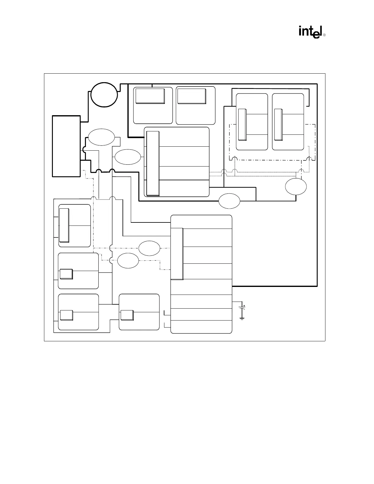
Figure 12-1. Power Delivery Example
Vcc
(CPU Core)
Voltage(DP) = 1.30 -1.50 V
Icore(max) = 63 A (DP)
Processor
VddA
(I/O)
3.3V
IvddA(max) = 280mA
Vdd
(Clock Core)
3.3V
Ivdd(max) = 280mA
C
K
4
0
8
B
Processor
Vcc_3.3
(Core Periphery) 3.3 V
Icc_3.3(max) = 420 mA
VccSus_3.3
(Resume I/O) 3.3 V
IccSus_3.3(max) = 14.01 mA
VccRTC (RTC)
2.0 V - 3.3 V (Battery)
IccRTC(max) = 4 µA
Vcc_1.8
(Core Logic) 1.8 V
Icc_1.8(max) = 550 mA
VccSus_1.8
(Resume Logic) 1.8 V
IccSus_1.8(max) = 64 mA
VcpuIO
(CPU CMOS I/O)
VccP (def. by CPU)
IcccpuIO(max) = 45 mA
Vtt
(System Bus Termination)
Variable Voltage (1.3 – 1.475 V)
Ivtt (max) = 2.0A
Vddr
(DDR I/O)
2.5 V
Iddr(max) = 5.8 A
Vcore
(Core Logic)
1.2 V
Icore(max) = 3.1 A
1.8 V
11.63 A
CPU VID
1.175 –
1.500 V
128 A
1.8 Vsb
14.01 mA
1.2 V
3.1 A
Vref(A & B)
1.25 V
Iref = 4.2 mA
3.3 Vsb
64 mA
1.25 V
12.5 A
VttA
VttB
VrefA
5VRef
5 V
IccV5Ref(max) = 10 µA
5 VrefSus
5 VSB
IccV5RefSu(max) = 10 µA
G
3
o
n
l
y
+12V
+3.3V
+5V
+5Vsb
SSI
Power
Supply
2.5 V
26 A
+5 V
+5 VSB
VrefB
Intel
®
ICH3-S
MCH
Vcc
(CPU Core)
Voltage(DP) = 1.30 -1.50 V
Icore(max) = 63 A (DP)
Vcc3.3
(PCI.X I/O)
3.3 V
Ivcc3.3(max) = 1.3 A
Vcc
(HI I/O & Core)
1.8 V
Icore(max) = 2.66 A
Intel
®
P64H2
Vcc3.3
(PCI.X I/O)
3.3 V
Ivcc3.3(max) = 1.3 A
Vcc
(HI I/O & Core)
1.8 V
Icore(max) = 2.66 A
P64H2
Vcc3.3
(PCI.X I/O)
3.3 V
Ivcc3.3(max) = 1.3 A
Vcc
(HI I/O & Core)
1.8 V
Icore(max) = 2.66 A
P64H2
Vdd
(Core)
2.5 V
Ivdd(max) =
10.0 A
Vtt
1.25 V
Ivterm(max) =
6.25 A
Vref
1.25 V
Iref = 8µA
D
D
R
(A)
Vdd
(Core)
2.5 V
Ivdd(max) =
10.0 A
Vtt
1.25 V
Ivterm(max) =
6.25 A
Vref
1.25 V
Iref = 8µA
D
D
R
(B)