Design Guide 61
System Bus Routing Guidelines
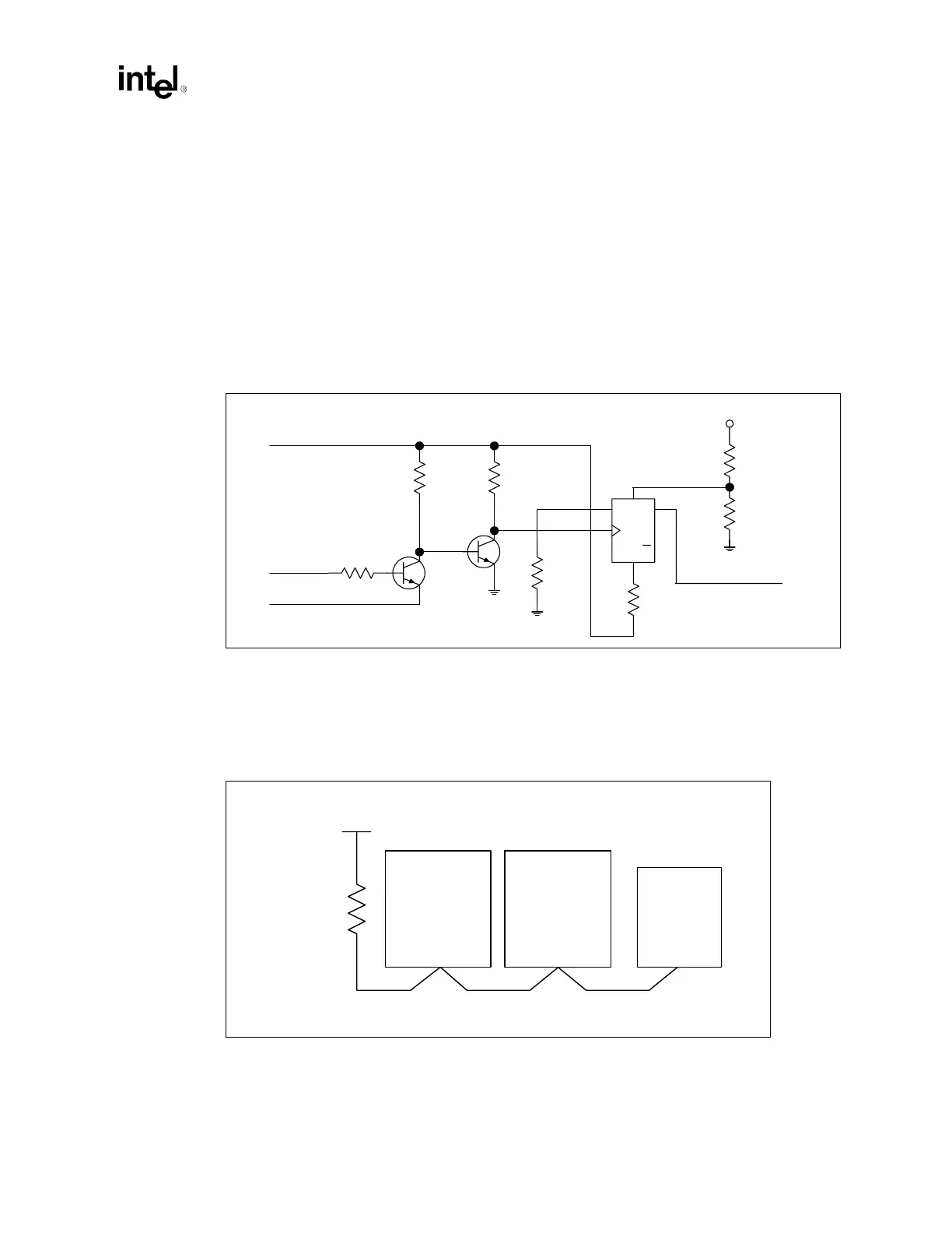
5.3.1.1 Proper THERMTRIP# Usage
To protect the processors from damage in over-temperature situations, power to the processor core
must be removed within 0.5 seconds of the assertion of THERMTRIP#. If power is applied to a
processor when no thermal solution is attached, normal leakage currents causes the die temperature
to rapidly rise to levels at which permanent silicon damage is possible. This high temperature
causes THERMTRIP# to go active. Use dual termination on the THERMTRIP# signal. Each
processor’s THERMTRIP# can be routed to its own receiver, or they can be wire-OR’d together. If
routed separately, each signal must be terminated at the receiver end only. All power supply
sources to all processors must be disabled when any installed processor signals THERMTRIP#. In
the reference schematic, the 74AHC74 flip-flop latches the THERMTRIP# signal HIGH after a
PWRGOOD assertion, and LOW after a THERMTRIP# assertion.
5.3.2 Asynchronous GTL+ Signals Driven by the Chipset
Follow the topology shown in Figure 5-6 when routing A20M#, IGNNE#, INIT#, LINT[1:0],
CPUSLP#, SMI# and STPCLK#. Do not route a stub when routing to the processors.
NOTES:
1. Trace Z
0
= 50 Ω.
2. Trace spacing = 10 mil.
Figure 5-5. Recommended THERMTRIP# Circuit
D
Q
Q
SET
CLR
3904
3904
10 kΩ1 k
Ω
62 Ω
12 V
74AHC74
VCC=3VSBY
3VSBY
VCC_CPU
THERMTRIP#
THERM_EN to VR
100 Ω
1 kΩ
1 kΩ
3.3 kΩ
Figure 5-6. Topology for Asynchronous GTL+ Signals Driven by the Chipset
Intel
®
ICH3-S
Processor 0 Processor 1
0.1" – 3.0"
0.1" – 9.0" 0.1" – 9.0"
VCC_CPU
200 Ω ± 5%