Design Guide 105
Intel
®
82870P2 (P64H2)
8.2.5.6 Hot Plug Muxed Signals in Single Slot Parallel Mode
The Hot Plug signals that connect to the controller are as follows:
1. HPx_SLOT [N] are pull-ups/pull-downs. When in dual slot parallel mode, the external logic that decodes the
three-state value of PCIXCAP from the card must actively drive these signals to either logic 1 or logic 0 to
overcome the value of the pull-up/pull-down, and must be tri-stated during reset and while the card is not
connected to avoid damaging the slot count value.
2. The P64H2 must drive this signal to its corresponding state shown in Table 8-11 in case the system is set up
for single slot parallel mode so that LEDs are in the appropriate state (off), and the Q-switches remain
disconnected. Note that the placement of the signals should be such that the value driven by the P64H2 in
dual slot parallel mode is the same value it would have driven if in serial mode.
3. In parallel mode, the BUSEN# and CLKEN# signals become active low instead of active high as they are
during serial mode.
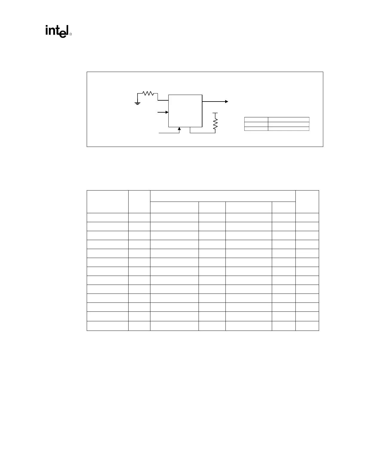
Figure 8-10. MUX Circuit Example
D
C
ENB
2:1 Multiplexer
VCC_3.3
PWROK
(PCIXCAP1 / PCIXCAP2) or HPxSLOT Strap
PCIXCAP1 / PCIXCAP2
1 k Ω
Truth Table
C (PWROK) D
HPxSLOT Strap
PCIXCAP1 / PCIXCAP2
0
1
S
1
S
2
This signal could be
pulled up to VCC_3.3
depending on the
strapping need.
8.2 kΩ
Table 8-10. Single Slot Parallel Mode Hot Plug Signal Table
Signal Type Muxed With Note
Bus A Ball # Bus B Ball #
HxSWITCHA I PA_IRQ[15] F4 PB_IRQ[15] F1
HxFAULTA# I PA_IRQ[14] E4 PB_IRQ[14] E1
HxPRSNT2A# I PA_IRQ[13] F5 PB_IRQ[13] D1
HxPRSNT1A# I PA_IRQ[12] E5 PB_IRQ[12] C1
HxM66ENA I/O PA_IRQ[11] D5 PB_IRQ[11] B1
HxPCIXCAP1A I HPA_SLOT[2] D20 HPB_SLOT[2] D23 1
HxPCIXCAP2A I HPA_SLOT[1] C20 HPB_SLOT[1] C23 1
HxRESETA# O PA_GNT[5] E22 PB_GNT[5] G4 2
HxGNLEDA O HPA_SOC A19 HPB_SOC A24 2
HxAMLEDA O HPA_SOL D19 HPB_SOL C22 2
HxBUSENA# O HPA_SORR# A18 HPB_SORR# A22 2, 3
HxCLKENA# O
HPA_SIL#
D24 HPB_SIL# D24 2, 3
HxPWRENA O
HPA_SOD
B19 HPB_SOD C24 2