Layout Checklist
216 Design Guide
14.3 Intel
®
ICH3-S Layout Checklist
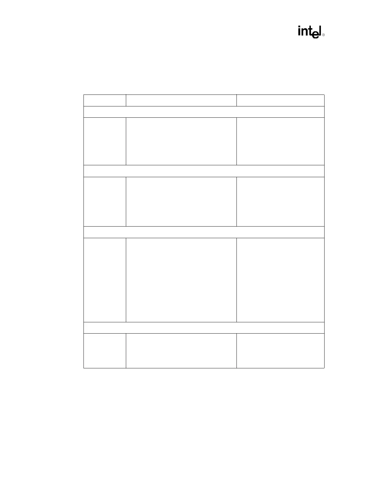
Table 14-3. Intel
®
ICH3-S Layout Checklist (Sheet 1 of 4)
Checklist Items Recommendations Comments
Processor Signals
A20M#
CPUSLP#
FERR#
IGNNE#
INIT#
LINT[1:0]
SMI#
STPCLK#
• See processor section of this checklist.
FWH Interface
Decoupling • 0.1 µF capacitors should be placed between
the VCC supply balls and the VSS ground
balls, and no less than 390 mils from the
VCC supply balls.
• 4.7 µF capacitors should be placed between
the VCC supply balls and the VSS ground
balls, and no less than 390 mils from the
VCC supply balls.
Hub Interface
General
Guidelines
• Board impedance must be 50 Ω ±10%.
• Traces must be routed 5 mils wide with
20 mils spacing (using given example 4-layer
4.5 mil prepreg stackup).
• To breakout of the MCH and ICH3-S
package, the hub interface signals can be
routed 5 on 5. Signals must be separated to
5 on 20 within 300 mils of the package.
• Maximum length of 20" (stripline routing).
• Data signals must be matched within
± 0.1" of the HI_STB differential pair.
• HIREF dividers should be placed no more
than 3.5 inches from MCH or ICH3-S.
• Refer to Section 7.3.
IDE Checklist
General
Guidelines
• Traces are routed 5 mil wide with 7 mil
spacing.
• Max trace length is 8" long.
• The maximum length difference between the
longest and shortest trace length is 0.5".
• Refer to ATA ATAPI-4
specification.
• Refer to Section 9.1.3 and
Section 9.1.4.