I/O Controller Hub
120 Design Guide
9.1.2 Cable Detection for Ultra ATA/66 and Ultra ATA/100
The ICH3-S IDE Controller supports PIO, Multi-word (8237 style) DMA and Ultra DMA modes 0
through 5. The ICH3-S must determine the type of cable that is present to configure itself for the
fastest possible transfer mode the hardware can support.
An 80-conductor IDE cable is required for Ultra DMA modes greater than 2 (Ultra ATA/33). This
cable uses the same 40-pin connector as the old 40-pin IDE cable. The wires in the cable alternate:
ground, signal, ground, signal, ground, signal, ground, and so on. All the ground wires are tied
together on the cable (and they are tied to the ground on the motherboard through the ground pins
in the 40-pin connector). This cable conforms to the Small Form Factor Specification SFF-8049.
This specification can be obtained from the Small Form Factor Committee.
To determine if Ultra DMA modes greater than 2 (Ultra ATA/33) can be enabled, the ICH3-S
requires the system software to attempt to determine the cable type used in the system. If the
system software detects an 80-conductor cable, it may use any Ultra DMA mode up to the highest
transfer mode supported by both the chipset and the IDE device. If a 40-conductor cable is
detected, the system software must not enable modes faster than Ultra DMA Mode 2
(Ultra ATA/33).
Intel recommends that cable detection be performed using a combination Host-Side/Device-Side
detection mechanism.
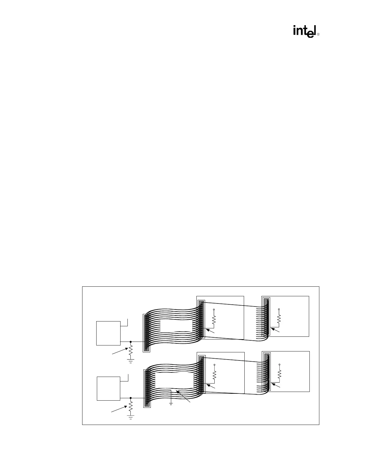
9.1.2.1 Combination Host-Side/Device-Side Cable Detection
Host side detection (described in the ATA/ATAPI-4 Standard, Section 5.2.11) requires the use of
two GPI pins (one for each IDE channel). The proper way to connect the PDIAG#/CBLID# signal
of the IDE connector to the host is shown in Figure 9-1. All IDE devices have a 10 kΩ pull-up
resistor to 5 V on this signal. Not all of the GPI and GPIO pins on the ICH3-S are 5 V tolerant. A
10 kΩ
± 5% pull-down resistor on PDIAG#/CBLID# is required to prevent the GPIO from floating
if a device is not present. The pull-down resistor also allows for the use of a non-5 V tolerant
GPIO.
Figure 9-1. Combination Host-Side/Device-Side IDE Cable Detection
80-conductor
IDE cable
IDE drive
5 V
Intel
®
ICH3-S
GPIO
GPIO
Open
IDE drive
5 V
40-conductor
cable
IDE drive
5 V
PDIAG#
Intel
®
ICH3-S
GPIO
GPIO
IDE drive
5 V
PDIAG#
PDIAG#PDIAG#
10 kΩ
10 kΩ
To secondary
IDE connector
PDIAG#/
CBLID#
PDIAG#/
CBLID#
10 kΩ
10 kΩ
10 kΩ
10 kΩ
Resistor required for
non 5V tolerant GPI
To secondary
IDE connector
Resistor required for
non 5V tolerant GPI