Design Guide 43
Platform Clock Routing Guidelines
4.1.2.1 CLK66 Skew Requirements
Traces going to the P64H2 could have up to two connectors. Designers should keep in mind that all
Total Lengths are referenced to the MCH length (“X”) and assume no connector. Each connector is
equivalent to 0.60 inches of trace. Adding a single connector on the P64H2 trace would reduce the
motherboard trace length by the card length “Z” to X – 0.34” – 0.60” – Z = X – 0.94” – Z (refer
to Figure 4-8). In addition, some OEMs might consider having the components on a riser, in which
case the riser card trace length designator “Y” should also be accounted for as yet another factor. In
this case the last equation would become X – 0.34” – 0.60”– Z – 0.60”– Y = X – 1.54”–Y – Z
(refer to Figure 4-9). Note that if a riser is used, the motherboard clock trace must be designed for
the specific riser card trace length and connector.
NOTES:
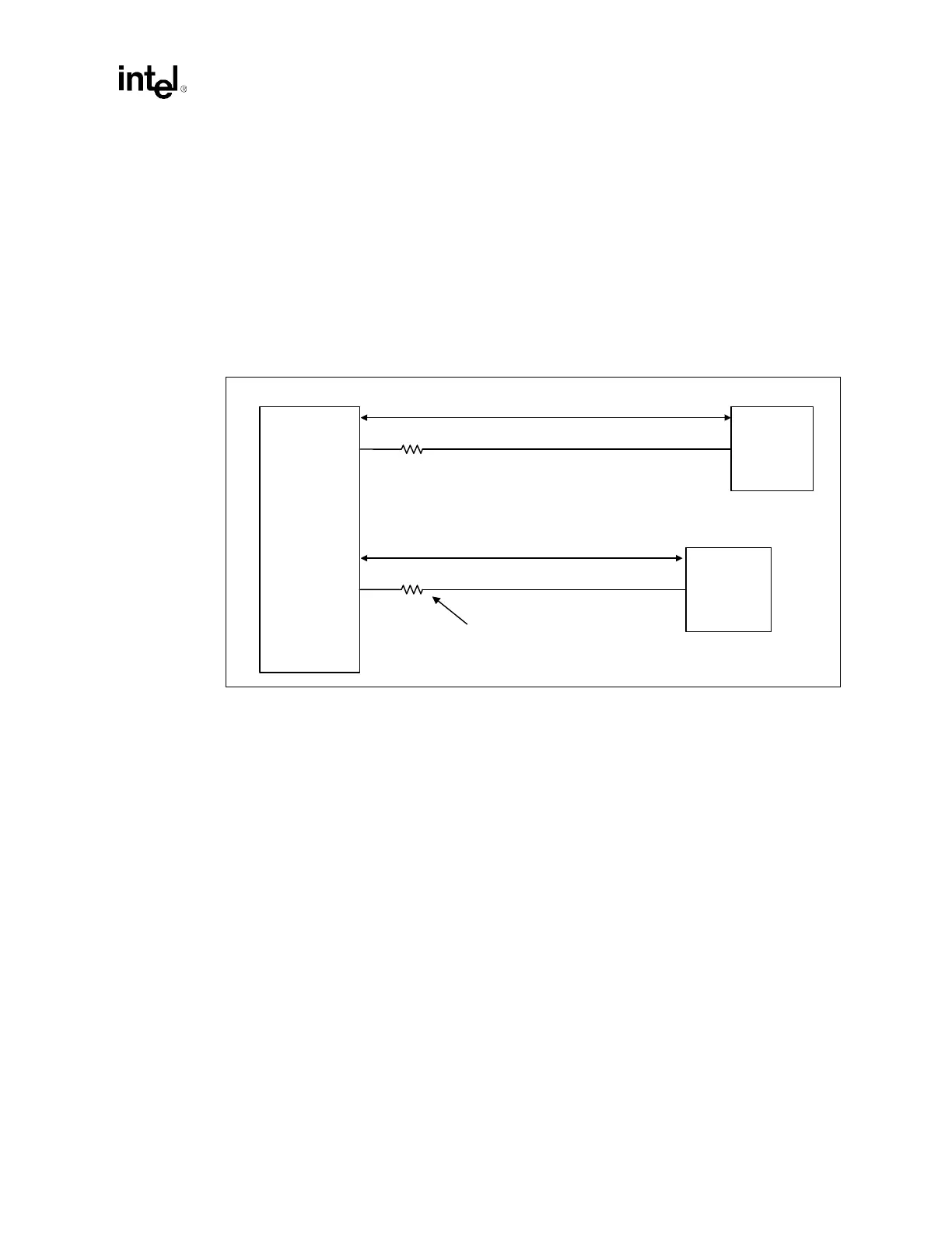
1. All lengths must be matched within 100 mils of target length.
2. 66 MHz clock lines routed with 25 mils isolation from any other signal.
3. Length from CK408B to MCH must be between 3” and 9.5”.
Figure 4-7. Clock Skew Requirements
43 Ω
Total Length = X
Total Length = X - 0.34"
CK408B
MCH
Intel
®
P64H2
Resistor must be within
500 mils of CK408B
43 Ω