Platform Clock Routing Guidelines
44 Design Guide
NOTES:
1. All lengths must be matched within 100 mils of target length.
2. 66 MHz clock lines routed with 25 mils isolation from any other signal.
3. Length from CK408B to MCH must be between 3” and 9.5”.
4. Each connector is equivalent to ~ 0.60” of trace.
5. Z is the card trace length.
NOTES:
1. All lengths must be matched within 100 mils of target length.
2. 66 MHz clock lines routed with 25 mils isolation from any other signal.
3. Length from CK408B to MCH must be between 3” and 9.5”.
4. Each connector is equivalent to ~ 0.60" of trace.
5. Each riser is equivalent to ~0.60 + Y where Y is the riser card trace length.
6. The riser must be built with the CLK66 trace length matched to the motherboard routed length.
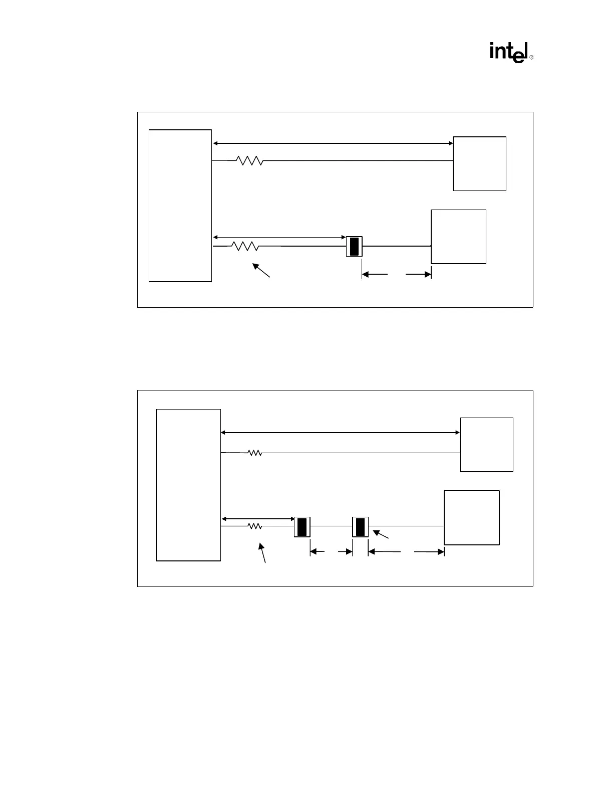
Figure 4-8. Example of Adding a Single Connector
Total Length = X
43 Ω
MCH
Intel
®
P64H2
43 Ω
Z
Motherboard Trace Length
= X - 0.34" - 0.60" - Z
= X - 0.94" - Z
Resistor must be within
500 mils of CK408B
CK408B
Figure 4-9. Example of Adding Two Connectors and/or a Riser
Total Length = X
Connector
CK408B
MCH
Intel
®
P64H2
43 Ω
43 Ω
YZ
Motherboard Trace Length
= X - 0.34" - 0.60" - Z - 0.60" - Y
= X - 1.54" - Z - Y
Resistor must be within 500
mils of CK408B