EMI and Mechanical Design Considerations
158 Design Guide
Utilization of the DC grounding strips requires ground pads around the mounting holes for the
retention mechanism. Metal inserts will be pre-assembled to the retention modules to establish DC
contact between heatsink base plate and the motherboard ground. The inserts will be grounded to
the baseboard at mounting hole ground pads. Fingers on top of the insert will connect to the base of
the heatsink. The requirements for the DC grounding insert are as follows:
• All four RM mounting holes must have ground pad rings.
• Ground pad annular ring should be no less than 125 mils wide. Try to cover the entire keep-out
zone, if possible. See Figure 11-8 for better dimensions.
• Place 8–12 vias in the annular ring, which connects the pad to internal ground planes.
• Anodizing or any form of insulated coating of the heat sink is strongly discouraged.
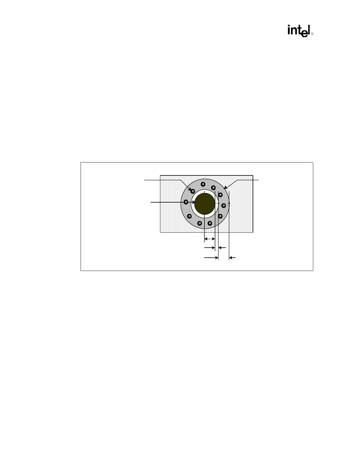
Refer to Figure 11-8 for specific details regarding the required ground pads.
Figure 11-8. Retention Mechanism Ground Ring
80 mils
15 mils
125 mils
RM Mounting Hole
Ground Ring
VIA