Design Guide 177
Platform Power Delivery Guidelines
12.2.11 Component Models
Acquire component models from their respective manufacturers. Intel cannot guarantee the
specifications of other manufacturers’ components. This section contains some of the models
developed by Intel for internal simulations.
12.2.12 Measuring Transients
Intel recommends the following guidelines when measuring the transients on VCC_CPU. The
measurement should be performed across the VCC_CPU and VSS pins on the processor socket.
Use an oscilloscope with 500 MHz bandwidth, 1.5 pF maximum probe capacitance, and 1 MΩ
minimum impedance. The maximum length of ground wire on the probe should be less than 5 mm.
Ensure that external noise from the system is not coupled on the scope probe. Some probes have a
very significant level of inherent noise. Attempt to minimize noise by investigating different
probes. Use a differential probe to make the voltage measurements. The bandwidth of the probe
should be no less than that of the oscilloscope. Ensure all connections from oscilloscope to
motherboard pin are good and have a very low contact resistance.
12.3 MCH Power Delivery Guidelines
The following guidelines are recommended for an optimal MCH power delivery. The main focus
of these guidelines is to minimize chipset power noise and signal integrity problems. The
guidelines are not intended to replace thorough system validation of products.
12.3.1 DDR_VTT (1.25 V) Decoupling
To reduce noise on the DDR termination voltage (1.25V) around the MCH, two 0.1 µF and two
0.01 µF capacitors per channel are recommended. Evenly distribute placement of decoupling
capacitors along the VTT plane around the MCH within 1 inch of the outer row of balls. Ceramic
0603 body type capacitors are recommended.
12.3.2 VCC_CPU (1.45 V Power Plane)
A maximum of five, 0.1 µF capacitors (minimum of four) are recommended (with 900 pH to
1.1 nH inductance) to be placed under the MCH for System Bus 1.50 V power plane decoupling.
The designer should evenly distribute placement of decoupling capacitors among the System Bus
interface signal field. In addition to the minimum decoupling capacitors under the MCH, the
designer should place a maximum of nine (9) evenly spaced capacitors for the System Bus, at least
seven (7) of which must be within 0.5 inch of the outer row of balls to the MCH.
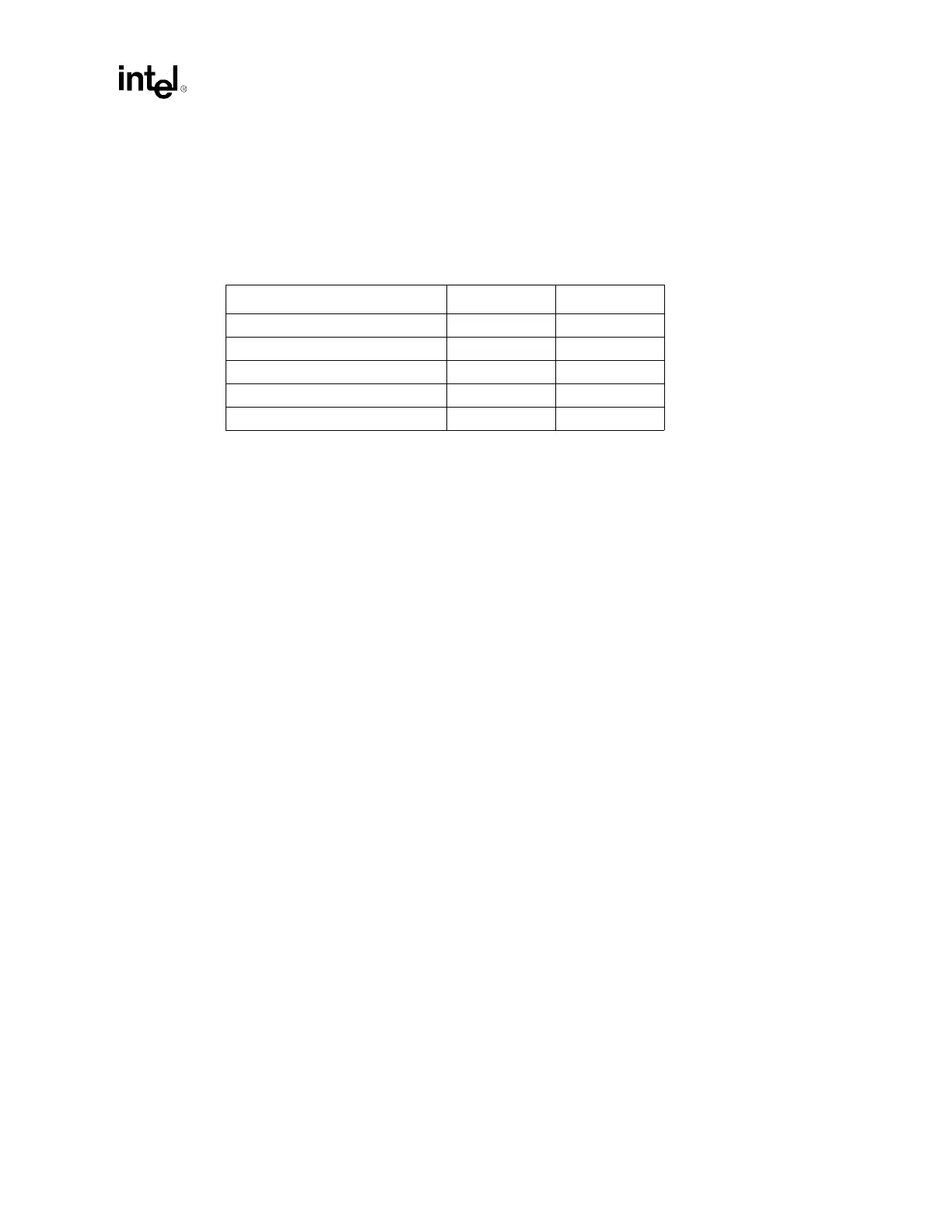
Table 12-7. Various Component Models Used at Intel (Not Vendor Specifications)
Component of Simulation ESR (Ω)ESL (nH)
0.1 µF Ceramic 0603 package 0.006 0.63
1 µF Ceramic 0805 package 0.080 0.702
10.0 µF Ceramic 1206 package 0.010 0.880
22.0 µF Ceramic 1210 package 0.010 0.880
560 µF OS-CONS 0.012 2.7