Design Guide 33
Platform Stack-Up and Component Placement Overview
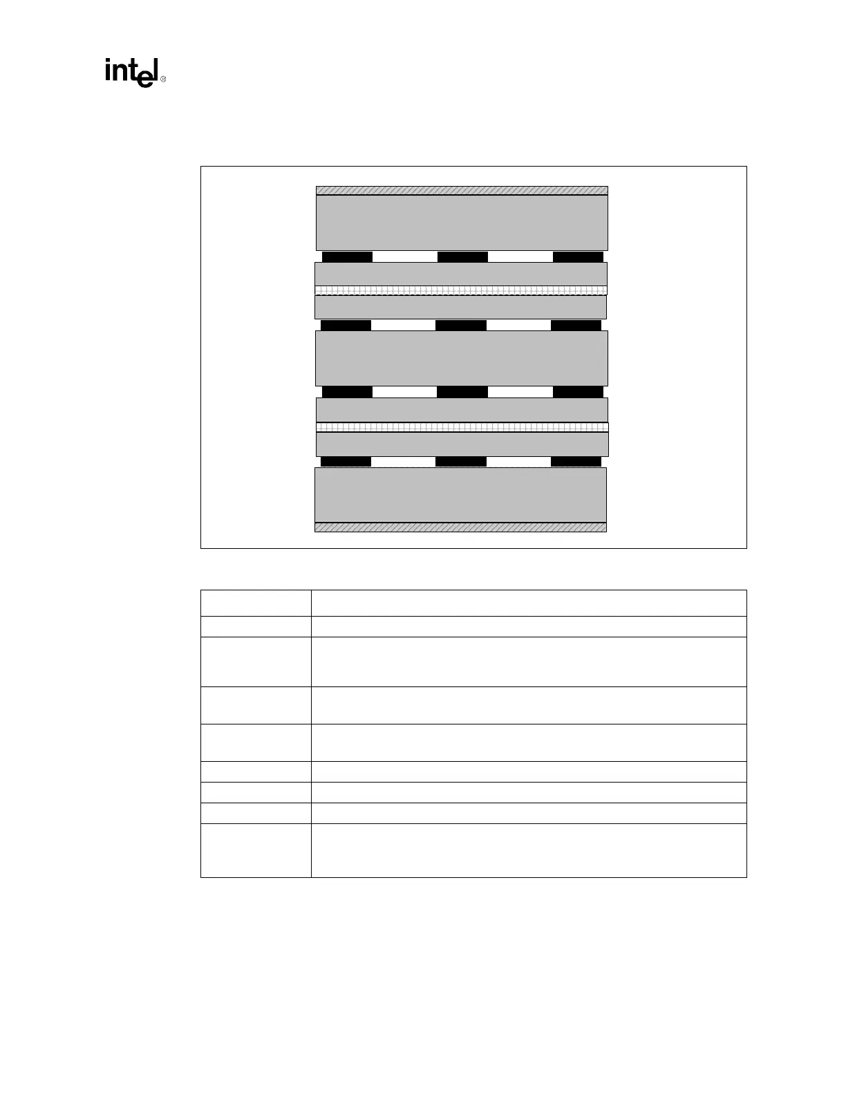
Figure 3-2. 8 Layer, 50 Ω Board with 5 mil Traces
Table 3-2. E7500 Chipset Customer Reference Board Requirements
Board Factor Recommendation
Material • Standard FR4 Tg 170 Epoxy.
Impedance
Requirements
• 50
Ω impedance ±10% Layers 2,4,5,7 (except lower left corner SCSI interface).
• SCSI interface 83
Ω single ended, 122 Ω differential pair ± 10% (layers 1 and 8
lower left corner).
Etch
• 5 mil trace width and space minimum inner/outer.
• SCSI interface; 6 mil separation within a pair, 20 mil space between adjacent pairs.
Finished Via Size
• Minimum via size is 0.014 mil finished in a 0.026 mil land with 0.040 mil antipad.
• Approximately 15,000 plated through holes total.
Finish • Solder Mask On Bare Copper (SMOBC)
Soldermask Type • SM-840 minimum web 0.004 mils.
Fabrication • Edge Routed.
Component
Technology
• Through hole / SMT.
• QFP, BGA, Front side.
• Discrete 0603, 0805 Back side.
Core 5.2 mil
Dielectric 9.6 mil
2.1 mil (1 oz + plating)
Power
Dielectric
SignalSignal Signal
Power
Dielectric
SignalSignal Signal
Ground
Main Core
Dielectric
SignalSignal Signal
Core
Ground
Dielectric
SignalSignal Signal
Core
1.4 mil (1 oz)
2.1 mil (1 oz + plating)
Core 5.2 mil
Dielectric 4.3 mil
Core 14.0 mil
Dielectric 9.6 mil
Dielectric 4.3 mil
Layer 1
Layer 2
Layer 3
Layer 4
Layer 5
Layer 6
Layer 7
Layer 8
1.4 mil (1 oz)
1.4 mil (1 oz)
1.4 mil (1 oz)
1.4 mil (1 oz)
1.4 mil (1 oz)