Design Guide 143
I/O Controller Hub
9.7.3.3 Intel
®
82562ET/EM Termination Resistors
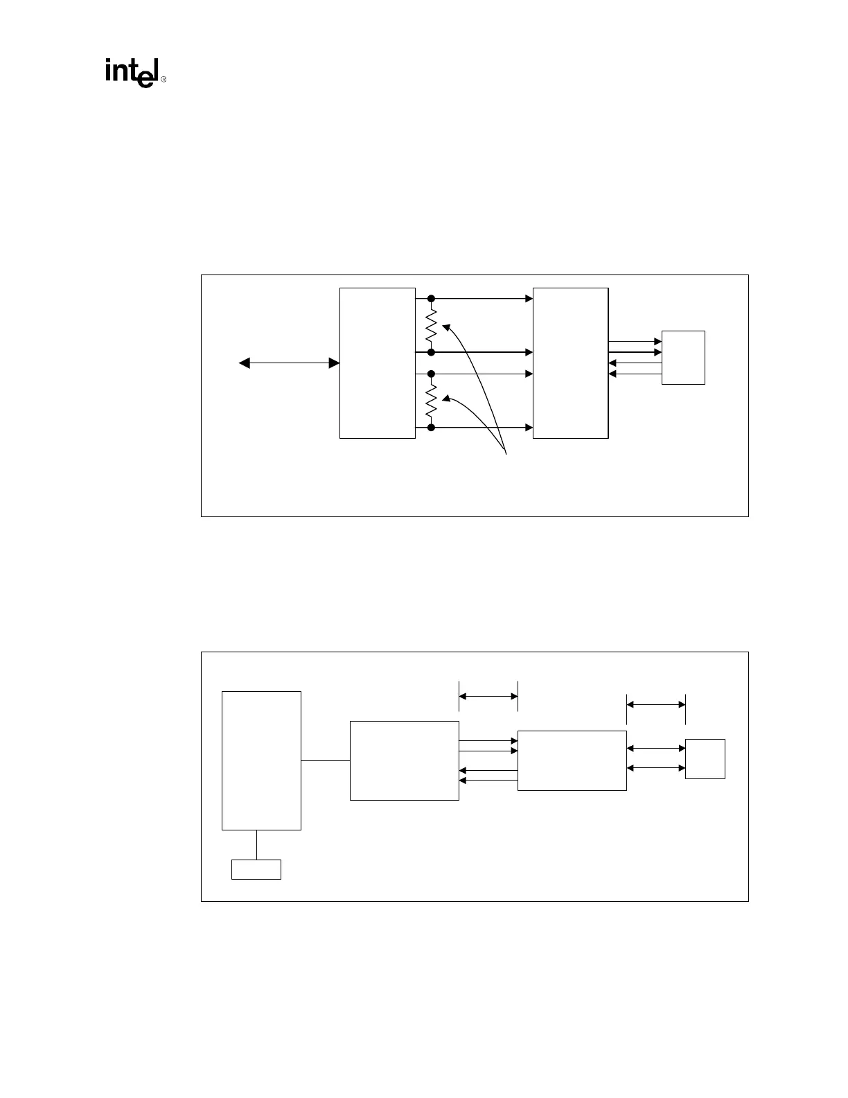
The 100 Ω ± 1% resistor used to terminate the differential transmit pairs (TDP/TDN), and the
121 Ω ± 1% resistor used to terminate the differential receive pairs (RDP/RDN) should be placed
as close to the Platform LAN connect component (82562ET or 82562EM) as possible. This is due
to the fact that these resistors are terminating the entire impedance that is seen at the termination
source (i.e., 82562ET), including the wire impedance reflected through the transformer.
9.7.4 Critical Dimensions
There are two dimensions to consider during layout. Distance 'A' from the line RJ45 connector to
the magnetics module, and distance 'B' from the 82562ET or 82562EM to the magnetics module.
The combined total distances A and B must not exceed 2 inches. (See Figure 9-20.)
Figure 9-19. Intel
®
82562ET/EM Termination
Intel
®
82562ET
Magnetics
module
RJ45
Place termination resistors as
close as possible to 82562ET.
LAN Connect
Interface
Figure 9-20. Critical Dimensions for Component Placement
Intel
®
82562ET
Intel
®
ICH3-S
EEPROM
Magnetics
Module
Line
RJ45
B < 1"
A < 1"