Design Guide 193
Schematic Checklist
13.2 MCH Schematic Checklist
L
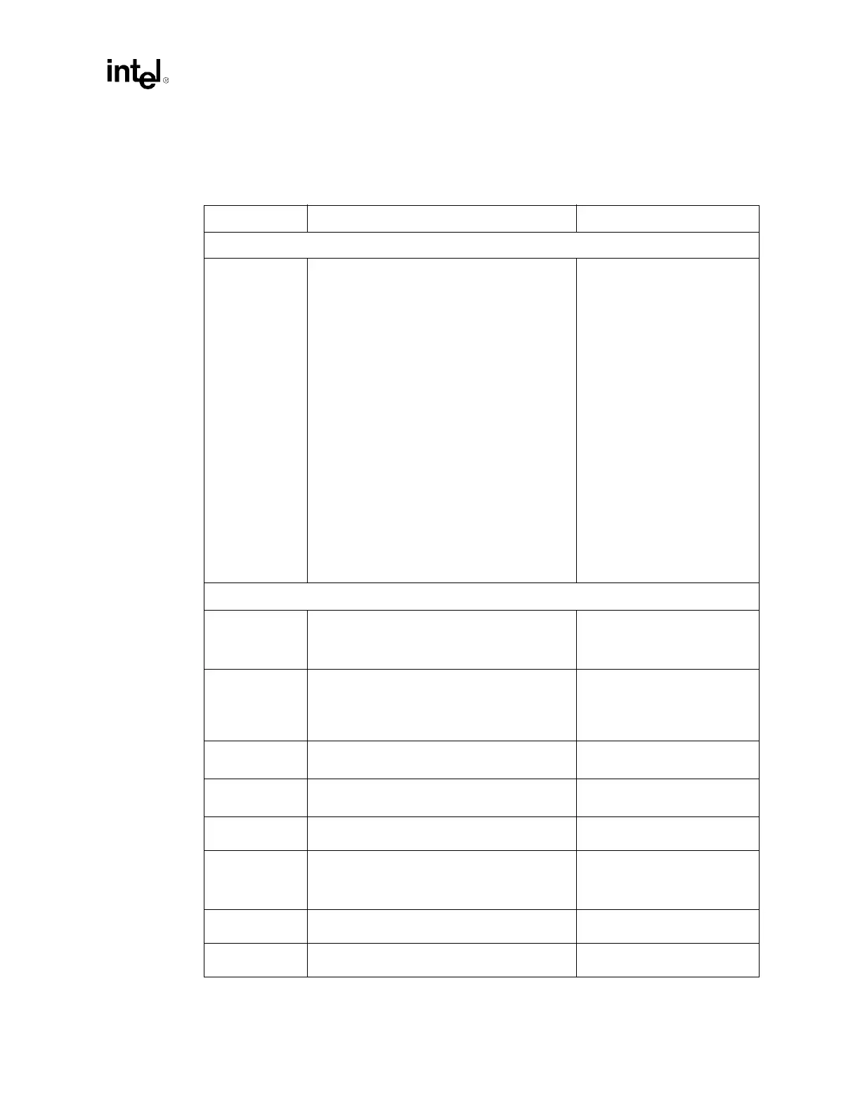
Table 13-2. MCH Schematic Checklist (Sheet 1 of 3)
Checklist Items Recommendations Comments
Host Interface
ADS#
AP[1:0]
BINIT#
BNR#
BPRI#
BREQ0#
1
CPURST#
2
DBI[3:0]#
DBSY#
DEFER#
DP[3:0]#
DRDY#
HA[35:3]#
3
HD[63:0]#
4
HADSTB[1:0]#
5
HDSTBN[3:0]#
6
HDSTBP[3:0]#
7
HIT#
HITM#
HLOCK#
HREQ[4:0]#
8
HTRDY#
9
RS[2:0]#
RSP#
XERR#
10
• See processor section of this checklist.
DDR Interfaces A & B / Connector
DQ[63:0]
CB[7:0]
DQS[17:0]
• Place a 10
Ω ± 2% series resistor between
MCH and first DIMM. Resistor Packs can be
used. Terminate these signals to DDR VTERM
(1.25 V) through a 22
Ω ± 2% resistor.
• Signal Integrity.
• Refer to Section 6.2.
MA[12:0]
BA[1:0]
RAS#
CAS#
WE#
• Terminate these signals to DDR VTERM
(1.25 V) through a 22
Ω ± 2% resistor.
• Refer to Section 6.4.
CS[7:0]# • Terminate these signals to DDR VTERM
(1.25 V) through a 22
Ω ± 2% resistor.
• Signal Integrity.
• Refer to Section 6.5.
CMDCLK[3:0]
CMDCLK[3:0]#
• Connect directly to the corresponding DIMM. • Signal Integrity.
• Refer to Section 6.3.
CKE • Terminate CKE to DDR VTERM (1.25 V)
through a 22
Ω ± 2% resistor.
• Refer to Section 6.6.
RCVENIN#
RCVENOUT#
• Route RCVENOUT# to RCVENIN#. Place a
47
Ω ± 2% parallel resistor to DDR VTERM as
close as possible to the MCH on the
RCVENIN# side. Refer to Figure 6-13.
• Refer to Section 6.7.
DDRCOMP • Pull-up to DDR VTERM (1.25 V) through a
6.81
Ω ± 1% resistor.
• Refer to Section 6.8.
DDRCVOL
DDRCVOH
• Connect as shown in Figure 6-15. • Refer to Section 6.8.