Design Guide 163
Platform Power Delivery Guidelines
For the processor, VCCMAX = 1.500 V and SM_VCC_CPU = 3.3 V. The VCCA supplies power
to the processor core and on-die termination used for the AGTL+ bus.
VCCIOPLL, VCCA, and VSSA are the power supplies to the internal PLL. VCCIOPLL,VCCA
and VSSA must be connected to VCC_CPU through a discrete RLC filter as described in
Section 12.2.8. Refer to the Intel
®
Xeon™ Processor with 512 KB L2 Cache at 1.80 GHz, 2 GHz,
and 2.20 GHz Datasheet for the pin location of these voltages.
12.2.1.2 Voltage Tolerance
Refer to the Intel
®
Xeon™ Processor with 512 KB L2 Cache at 1.80 GHz, 2 GHz, and 2.20 GHz
Datasheet for voltage tolerance specifications. Failure to meet these specifications on the low-end
tolerance results in transistors slowing down and not meeting timing specifications. Not meeting
the specifications on the high-end tolerance can cause damage or reduce the life of the processor.
Unlike the previous Intel processors (the Pentium
III Xeon processors), the Intel Xeon processor
specifications for VCC_CPU and ICC are not independent. The VID definition is changed to
absolute maximum VCC_CPU allowed. ICC_MAX is measured at VCC_MAX.
12.2.2 Processor Current Requirements
The processor allows the use of low power states to reduce power consumption by stopping the
clock to specific internal sections of the processor and the BCLK depending on each particular
state. This can create load change transients as high as 450 amps per microsecond (450 A/µs slew
rate) on VCC_CPU at the socket pins. The shape of the current through the processor socket during
a transient usually does not have a constant slope due to the high-frequency filtering by the
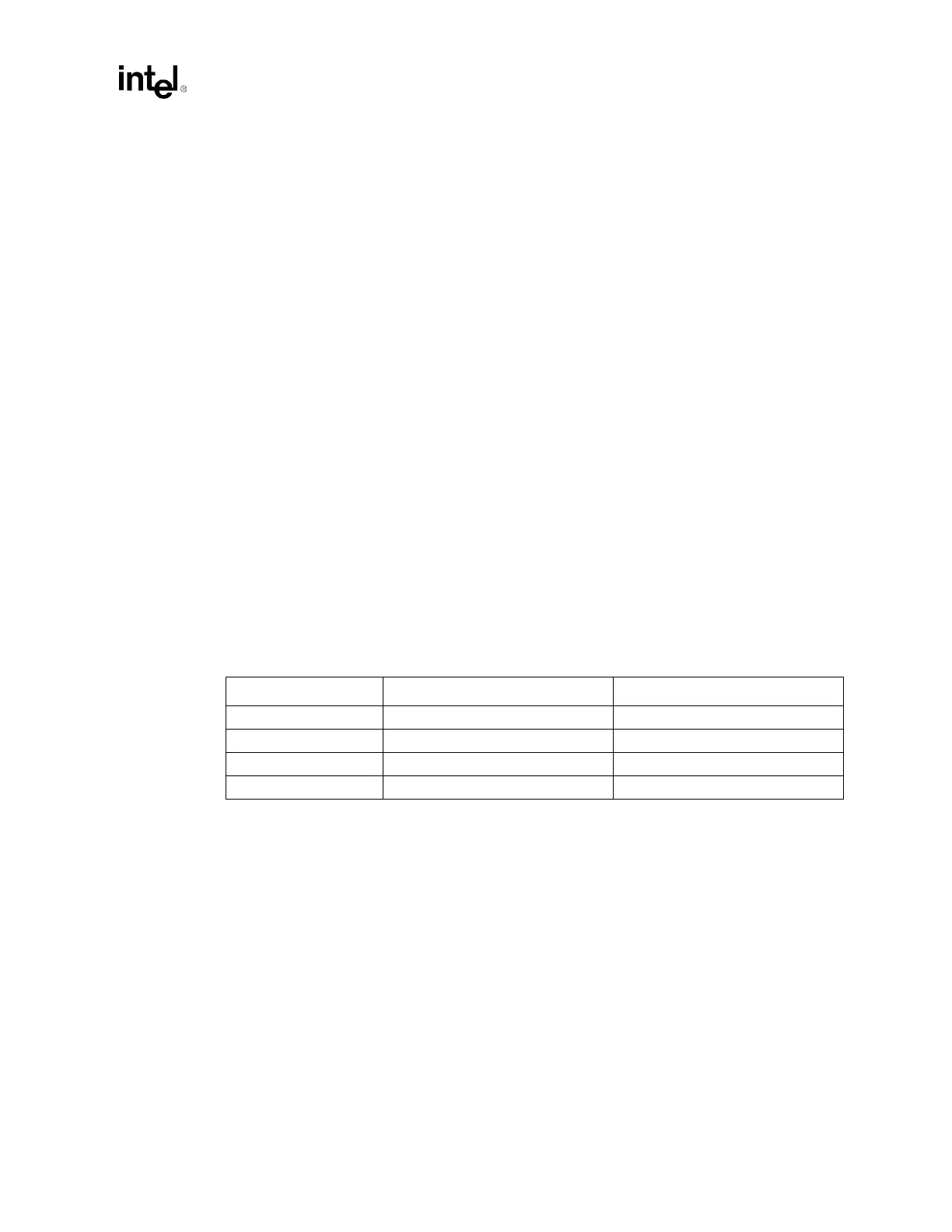
package decoupling. Table 12-2 shows the maximum current and current step size per processor.
12.2.3 Power Delivery Layout Requirements
Note that the Voltage Regulator must be placed as close as possible to the processor, on the side of
the socket that has the greatest density of power and ground pins.
The maximum distance between each processor and its voltage regulator module or the output
inductors of an embedded Voltage Regulator should not be greater than 1.5 inches. To be more
specific, the distance between the facing edges of the Voltage Regulator connector and the socket
should be no more than 0.5 inch.
Processor VCC_CPU static and transient tolerances and the corresponding Voltage Regulator
tolerances assume power distribution paths with resistances no greater than 0.4 mΩ and
inductances no greater than 0.1 nH. Meeting these limits can be a challenge because of system
layout constraints.
Table 12-2. Processor Current Step Parameters
Processor Frequency Maximum Step Size per Processor Maximum Current per Processor
1.8 GHz 26.5 A 41.9 A
2.0 GHz 29.3 A 44.7 A
2.2 GHz 32.1 A 47.6 A
FMB 46.3 A 61.5 A