Design Guide 23
Introduction
1.3.3 Bandwidth Summary
Table 1-3 describes the clock maximum speed, sample rate, and bandwidth for each of the
interfaces in the E7500 chipset based platform.
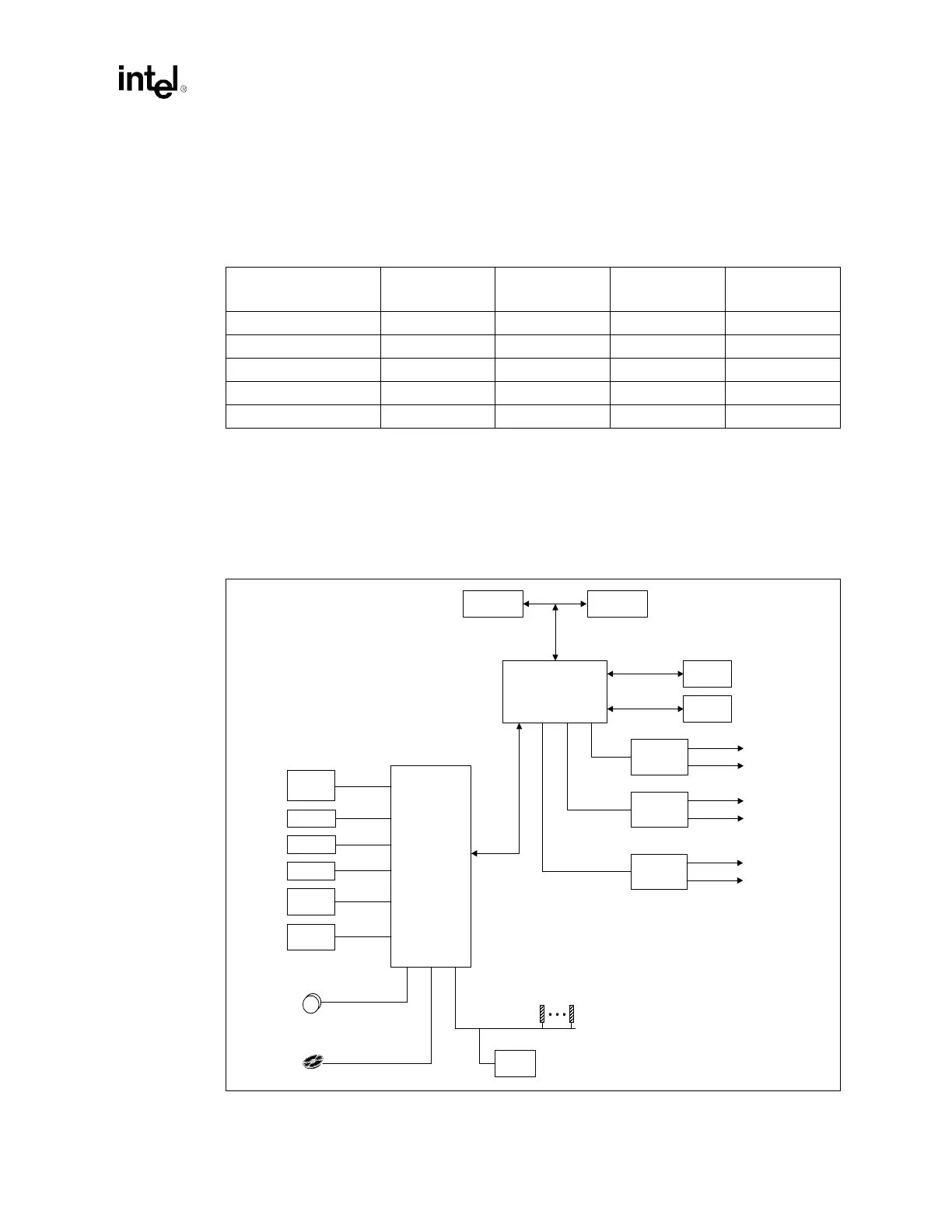
1.3.4 System Configurations
Figure 1-1 illustrates an example E7500 chipset-based system configuration for server platforms
using Xeon processors.
Table 1-3. Platform Maximum Bandwidth Summary
Interface
Clock Speed
(MHz)
Samples per
Clock
Data Width
(Bytes)
Bandwidth
(MB/s)
System Bus (Data) 100 4 8 3200
DDR Interface 100 2 16 3200
Hub Interface A 66 4 1 266
Hub Interface B, C, D 66 8 2 1066
PCI-X 133 1 8 1066
Figure 1-1. Example Intel
®
Xeon™ Processor with 512 KB L2 Cache / Intel
®
E7500 Chipset
Based System Configuration
Intel
®
ICH3-S
MCH
USB 1.1, 6 Ports
AC '97
Codec(s)
AC'97 2.1
1–4 FWHs
10/100 LAN
Controller
4 IDE Devices
UltraATA/100
System Memory
GPIOs
ProcessorProcessor
SMBus 1.1
SMBus
Devices
LPC I/F
Super I/O
PCI Bus
PCI
Slots
PCI
Agent
Intel®
P64H2
PCI / PCI-X
PCI / PCI-X
Hot Plug
16-bit
HI 2.0
P64H2
PCI / PCI-X
PCI / PCI-X
Hot Plug
16-bit
HI 2.0
200 MHz
DDR
200 MHz
DDR
P64H2
PCI / PCI-X
PCI / PCI-X
Hot Plug
16-bit
HI 2.0
8-bit
HI 1.5