Design Guide 157
EMI and Mechanical Design Considerations
11.3.1 Grounding Techniques
In an effort to be proactive regarding electromagnetic interference (EMI) reduction, Intel is
enabling a reduction technique for Intel Xeon processor-based systems. The solution is comprised
of a metal grounding frame that contacts the heatsink on all four sides and provides grounding to
the motherboard. A second, optional solution is the DC grounding strips, which provide the
heatsink a two point electrical connection to ground and insert into the retention mechanism pieces.
The grounding frame for the Intel Xeon processor is meant to provide grounding of AC currents
seen on the heatsink, and has been shown to be the most effective design in EMI reduction for the
processor. The metal frame will be installed after the processor and retention mechanisms have
been inserted. It will fit around the processor and inside of the retention mechanisms. Fingers on
the top of the metal frame will provide contact to the heatsink, and fingers along the bottom will
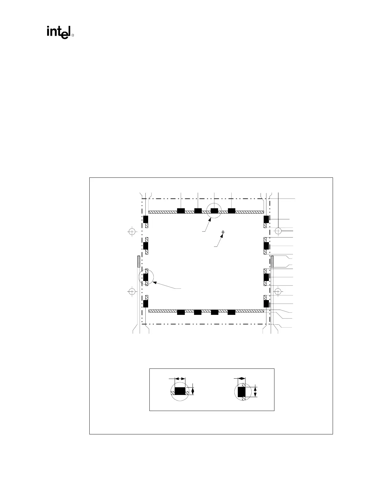
contact the ground pads on the motherboard. The grounding frame will require the placement of a
series of ground pads surrounding the processor, as shown in Figure 11-8.
Figure 11-7. EMI Ground Size and Location
2.920
3.030
3.080
.120
.170
.280
SEE DETAIL B
SEE DETAIL A
SOCKET PAD #1
LOCATION
3.000
.000
.200
.280
.324
.953
1.383
1.818
2.248
2.876
2.920
.992
.950
.550
.508
.326
.163
.000
.089
.262
.625
2.125
1.900
1.850
1.762
1.589
1.337
1.175
PAD LAYOUT IS SYMMETRIC ABOUT RETENTION MODULE HOLE
LOCATIONS IN BOTH DIRECTIONS
DETAIL A
.125
.100
.100
DETAIL B
.125