Design Guide 59
System Bus Routing Guidelines
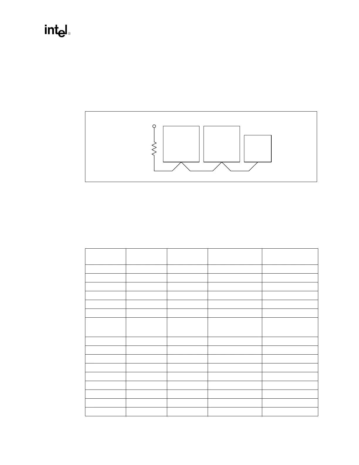
5.2.2 RESET# Topology
Since the processor does not contain on-die termination for the RESET# input signal, these
additional layout guidelines for the RESET# signal are required. The baseboard trace length from
Processor 0's pin to the termination resistor should be 0 to 1 inch.Follow the same routing
guidelines given for common clock signals listed above in this same section.
5.3 Routing Guidelines for Asynchronous GTL+ and
Miscellaneous Signals
Table 5-6 enumerates the remainder of the processor signals discussed in this document.
Figure 5-3. RESET# Topology
MCH
Processor 1Processor 0
VCC_CPU
0.1" - 1.0"
51 Ω ± 5%
3.0" - 10.1" 3.0" - 10.1"
Table 5-6. Asynchronous GTL+ and Miscellaneous Signals (Sheet 1 of 2)
Signal Name Type
Processor
I/O Type
Driven By Received By
A20M# Async GTL+ I ICH3-S Processor
BINIT# AGTL+ I/O Processor Processor
BR[3:1]# AGTL+ I Processor Processor
BR0# AGTL+ I/O Processor/MCH Processor/MCH
COMP[1:0] Analog I Pull-down Processor
FERR# Async GTL+ O Processor ICH3-S
IERR# Async GTL+ O Processor
External Logic (such as
Baseboard
Management Controller)
IGNNE# Async GTL+ I ICH3-S Processor
INIT# Async GTL+ I ICH3-S Processor
LINT[1:0] Async GTL+ I ICH3-S Processor
ODTEN Other I Pull-up / Pull-down Processor
PROCHOT# Async GTL+ O Processor External Logic
PWRGOOD Async GTL+ I External Logic Processor
SLP# Async GTL+ I ICH3-S Processor
SM_ALERT# SMBUS (3.3 V) O Processor/Controller Controller
SM_CLK SMBUS (3.3 V) I/O Processor/Controller Processor/Controller