Design Guide 129
I/O Controller Hub
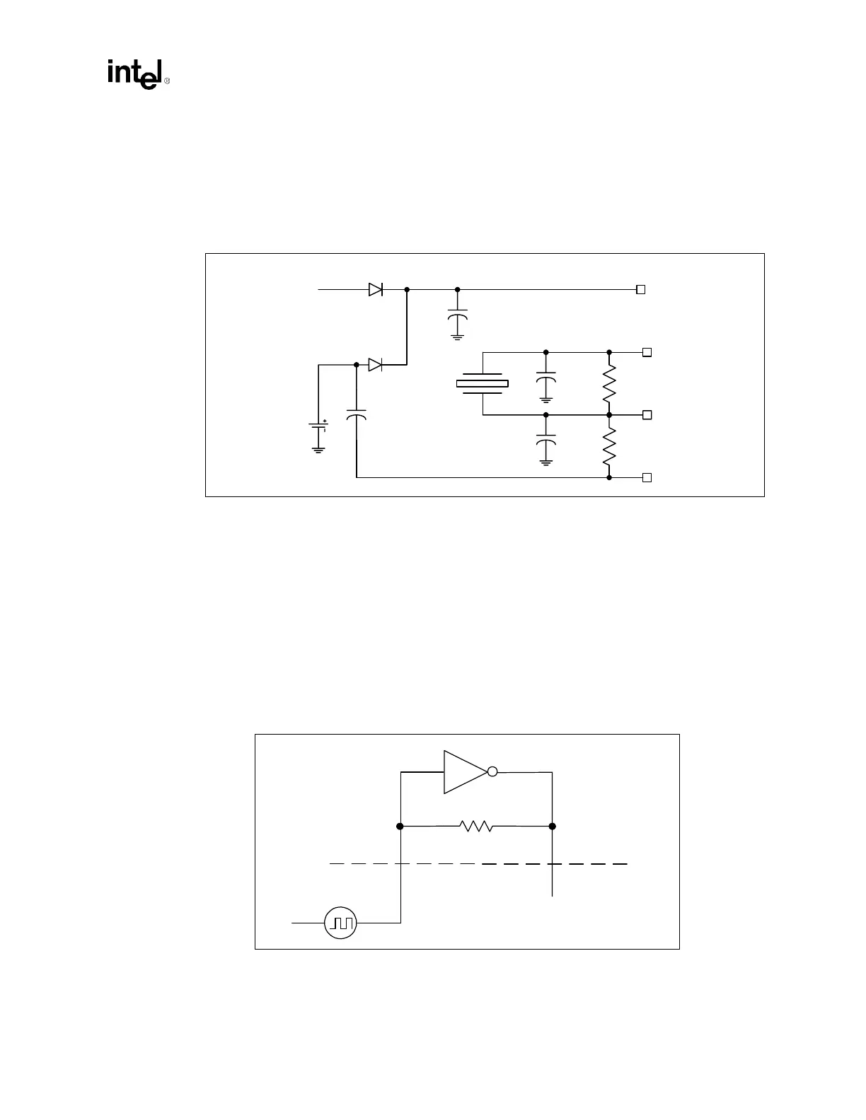
9.6.1 RTC External Circuit
The ICH3-S RTC module requires an external oscillating source of 32.768 kHz connected on the
RTCX1 and RTCX2 balls. Figure 9-10 documents the external circuitry that comprises the
oscillator of the ICH3-S RTC.
NOTES:
1. The exact capacitor values must be based on the crystal maker recommendation.
(Typical values for C1 and C2 are 18 pF for a crystal load of 12 pF.)
2. VCCRTC: Power for RTC Well
3. RTCX2: Feedback for the external crystal
4. RTCX1: Input to the internal oscillator
5. VBIAS: RTC BIAS Voltage – This pin is used to provide a reference voltage, and this DC voltage sets a
current, which is mirrored throughout the oscillator and buffer circuitry.
Note: Even if the ICH3-S internal RTC is not used, it is still necessary to supply clock inputs to RTCX1
and RTCX2 pins of the ICH3-S because other signals are gated with that clock in suspend modes.
However, in this case the frequency (32.768 kHz) of the clock inputs is not critical. A lower-cost
crystal can be used, or a single clock input can be driven into the RTCX1 pin with the RTCX2 pin
left as no connect; Figure 9-11 illustrates this. This is not a validated configuration with ICH3-S.
Figure 9-10. RTC External Circuitry
32.768 kHz
Xtal
C3
0.047 µF
VCCRTC
RTCX2
RTCX1
VBIAS
Vbatt
1 µF
3.3V Sus
C1
18 pF
C2
18 pF
R1
10 M
Ω
R2
10 M
Ω
Figure 9-11. RTC Connection When Not Using Internal RTC
5 MΩ
No
Connection
Internal
External
32 KHz
RTCX1 RTCX2