Hub Interface
90 Design Guide
Using the recommended stackup, the Hub Interface 1.5 data signal traces must be routed 5 mils
wide. There must be 15 mils spacing between traces (5/15). To break out of the MCH and ICH3-S
packages, the Hub Interface data signals can be routed 5/5. The signals must be separated to 5/15
within 0.3 inch of the package.
For Hub Interface 1.5 devices on the motherboard, each strobe signal trace must be the same
length, and each data signal trace must be matched within ± 0.1 inch.
7.3.2 Hub Interface 1.5 Generation/Distribution of Reference
Voltages
The nominal Hub Interface 1.5 reference voltage is 0.35 V ± 5%. The 8-bit Hub Interface on the
MCH has a dedicated HIVREF pin to sample this reference voltage. In addition to the reference
voltage, a reference swing voltage must be supplied to control buffer voltage swing characteristics.
The nominal Hub Interface 1.5 reference voltage swing must be 0.8 V ±
5% for the MCH and
0.7 V ±
5% for the ICH3-S. This voltage is sampled by the MCH using HISWING, and is sampled
by the ICH3-S using HITERM. (see Table 7-8). Both HISWNG and HITERM can be generated
locally with a single voltage divider circuit as shown in Figure 7-8.
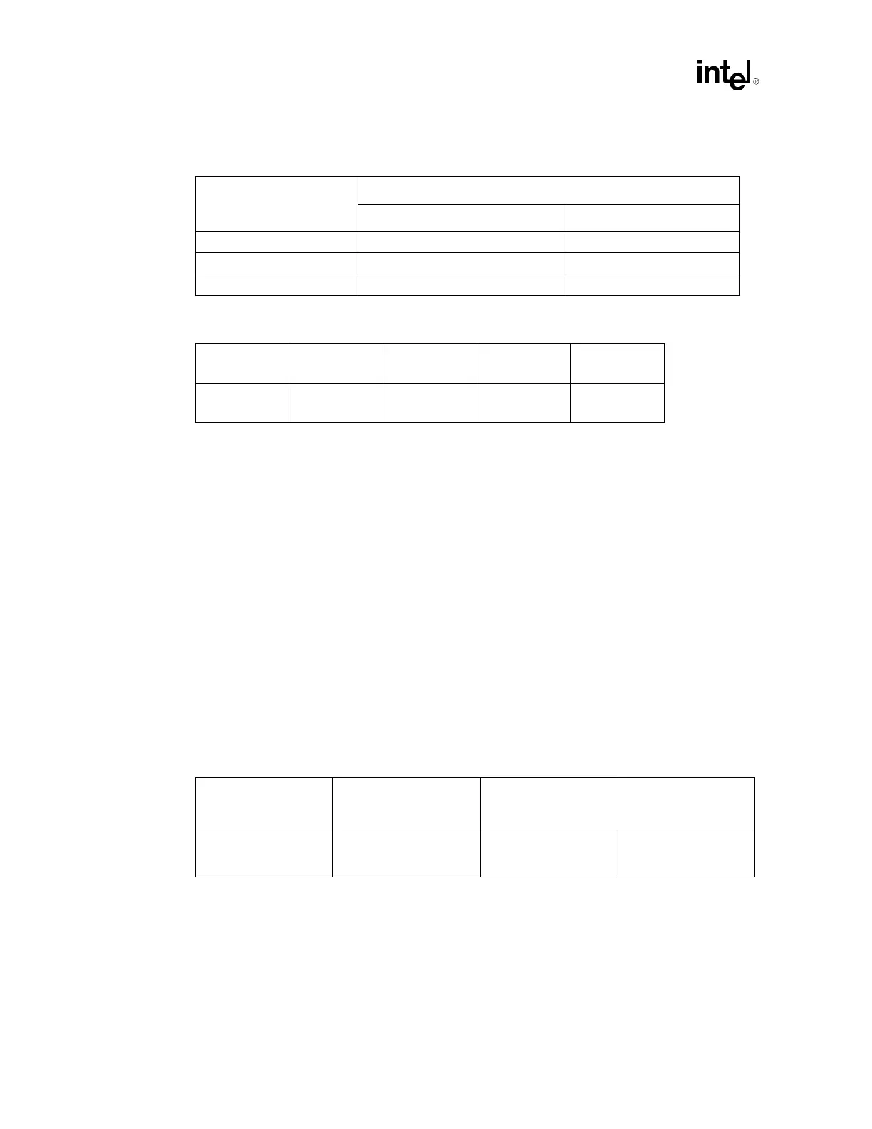
Table 7-6. Hub Interface 1.5 Signal Groups
Group
Signals
MCH Intel
®
ICH3-S
Common Clock Signals HI_A[11:8] HI[11:8]
Source Synchronous Signals HI_A[7:0], HI_STBF, HI_STBS HI[7:0], HI_STBF, HI_STBS
Miscellaneous Signals HIRCOMP_A, HISWNG_A, HIVREF_A HICOMP, HITERM, HIREF
Table 7-7. Hub Interface 1.5 Routing Parameters
System Type
Trace Length
Min-Max
Trace Z
0
Trace
Width/Spacing
Breakout
Width/Spacing
266 MHz 3” – 20” 50
Ω ± 10% 5/15 mils
5/5 mils
(max dist = 0.3”)
Table 7-8. Hub Interface 1.5 Reference Circuit Specifications
Reference Voltage
Specification (V)
Reference Swing Voltage
Specification (V)
1.2 V Voltage Divider
Circuit Recommended
Resistor Values (
Ω)
1.8 V Voltage Divider
Circuit Recommended
Resistor Values (Ω)
0.35 ± 5%
For ICH3-S = 0.7 ± 5%
For MCH = 0.8 ± 5%
R1 = 392 ± 1%
R2 = 499 ± 1%
R3 = 453 ± 1%
R4 = 261 ± 1%
R5 = 825 ± 1%