Design Guide 121
I/O Controller Hub
This mechanism allows the BIOS, after diagnostics, to sample PDIAG#/CBLID#. If the signal is
high, then a 40-conductor cable is present in the system and Ultra DMA modes greater than Mode
2 (Ultra ATA/33) must not be enabled.
If PDIAG#/CBLID# is detected low, then an 80-conductor cable may be in the system, or there
may be a 40-conductor cable and a legacy slave device (Device 1) that does not release the
PDIAG#/CBLID# signal as required by the ATA/ATAPI-4 standard. In this case, BIOS should
check the IDENTIFY DEVICE information in a connected device that supports Ultra DMA modes
higher than 2. If ID Word 93, bit 13 is a “1,” then an 80-conductor cable is present. If this bit is “0”
then a legacy slave (Device 1) is preventing proper cable detection, and BIOS should configure the
system as though a 40-conductor cable is present and notify the user of the problem.
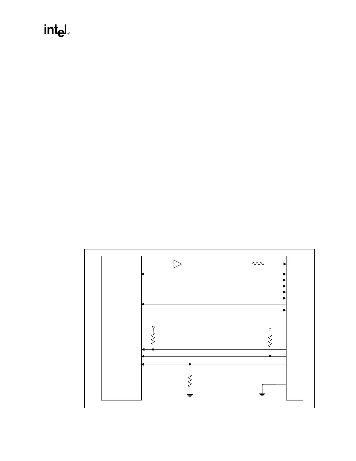
9.1.3 Primary IDE Connector Requirements
The requirements for the primary IDE connector are shown in Figure 9-2.
• A 22 Ω to 47 Ω series resistor is required on RESET#. The correct value should be determined
for each unique motherboard design, based on signal quality.
• An 8.2 kΩ to 10 kΩ pull-up resistor is required on IRQ14 to VCC_3.3.
• A 4.7 kΩ ± 5% pull-up resistor to VCC_3.3 is required on PIORDY.
• Series resistors can be placed on the control and data lines to improve signal quality. The
resistors are placed as close to the connector as possible. Values are determined for each
unique motherboard design.
• The 10 kΩ ± 5% resistor to ground on the PDIAG#/CBLID# signal is required on the Primary
Connector. This change is to prevent the GPIOx pin from floating if a device is not present on
the IDE interface.
NOTE:
1
Because of ringing, PCIRST# must be buffered.
Figure 9-2. Connection Requirements for Primary IDE Connector
CSEL
3.3 V
3.3 V
4.7 kΩ 8.2–10 kΩ
10 kΩ
PIORDY (PRDSTB/PWDMARDY#)
PDIAG# / CBLID#
IRQ14
GPIOx
Primary IDE Connector
Intel
®
ICH3-S
PCIRST#
1
PDD[15:0]
PDA[2:0]
PDCS[3,1]#
PDIOR#
PDIOW#
PDDREQ
PDDACK#
22–47 Ω
IDERST#