Design Guide 155
EMI and Mechanical Design Considerations
11.3 Retention Mechanism Placement and Keep-Outs
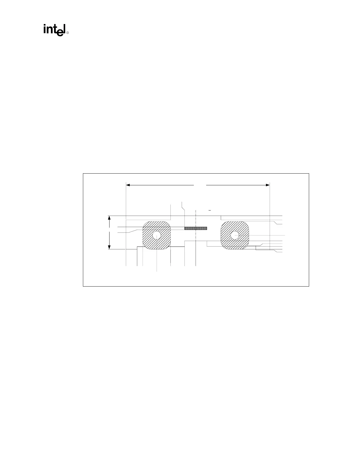
The retention mechanism (RM) for the Intel Xeon processor requires two keep-out zones: one for
the EMI ground pads, and another for a limited component height area under the RM as shown in
Figure 11-5. Figure 11-6 shows the relationship between the RM mounting holes and pin one of the
sockets; it also documents the ground pads and keep-outs. Figure 11-7 details the ground pad
locations and the associated limited height areas due to the ground frame.
The EMI ground pads under the retention mechanism must each have a minimum of eight vias
connecting the pad to the baseboard ground plane. The retention holes must be non-plated. It is not
necessary to have a ground pad on the secondary side of the baseboard when using the push-pin
fasteners. The push-pins protrude approximately 0.200 inch from the secondary side of the board.
The ground pads for the EMI ground frame must have a minimum of six vias each connecting the
pads to the ground plane. The suggested via size is 12 mils. This allows sufficient clearance to
route traces between the vias on the secondary side of the PCB or on internal layers.
Figure 11-5. Retention Mechanism Outline and Ground Pad Detail
(.755)
.174
.124
.755
.540
.275
.750
.550
.262
.000
.262
.415
(3.010)
.300
.277
.210
.190
.100
.000
.264
.302
.455
SYMMETRIC ¢