Design Guide 63
System Bus Routing Guidelines
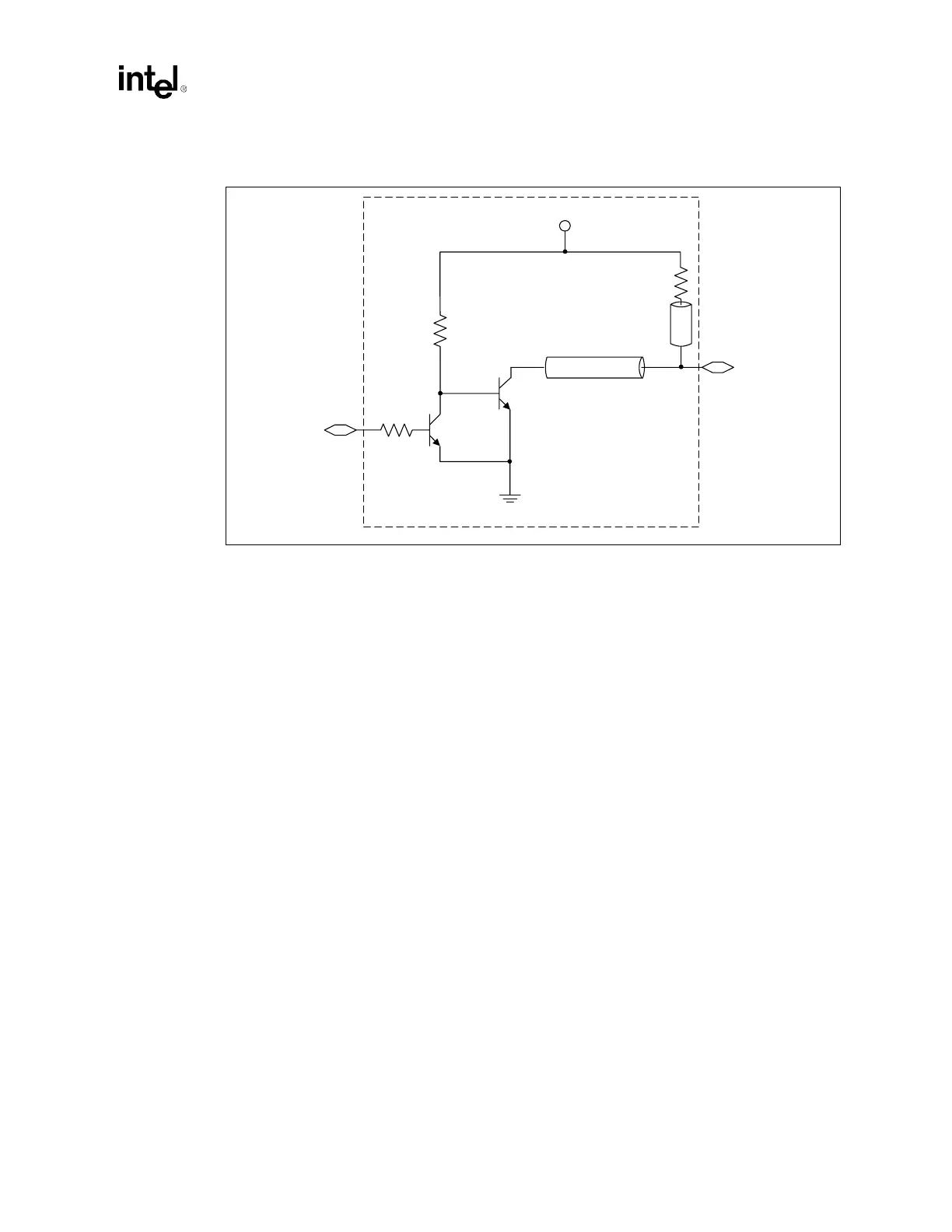
NOTE: T1 and T2 must be referenced to ground.
5.3.3 VID[4:0]
Route the VID[4:0] signals of the processor to the VID[4:0] inputs of the voltage regulator
controller. The voltage regulator controller should provide internal pull-up resistors for these
signals. Refer to the VRM 9.1 DC-DC Converter Design Guidelines and the specification of the
voltage controller specific to your design for further details.
Since both processors must operate at the same voltage, the designer should provide a way to check
the VID[4:0] signals to ensure a processor does not operate out of specification. (Refer to
Figure 12-3 for more information.
5.3.4 SMBus Signals
The SMBus signals provide access to the thermal sensor and memory device on the processor. The
signaling protocol used adheres to the specification of the System Management Bus. Refer to
Intel
®
Xeon™ Processor with 512 KB L2 Cache at 1.80 GHz, 2 GHz, and 2.20 GHz Datasheet for
details on the Xeon processor implementation and addressing scheme.
Connect the SM_ALERT#, SM_CLK, and SM_DAT signals to the SMBus controller in adherence
to the System Management Bus (SMBus) Specification, Version 1.1. These signals can be connected
to other processors on the same SMBus.
The SM_EP_A[2:0] signals set the SMBus address for the memory device on the processor. These
signals must be set at power up with a unique address per bus. They have an internal 10 kΩ ± 5%
pull-down. To pull the SM_EP_A[2:0] signals to a logic high level, connect each signal to a
100 Ω ± 5% resistor tied to SM_VCC. Refer to the section on SMBus Device Addressing in the
Processor datasheet for addressing details.
Figure 5-9. Voltage Translator Circuit
From Driver
To Receiver
3904
3904
Vcc of Receiver
300 Ω
± 5%
470 Ω
± 5%
T1
T2
T1 = 10" max
T2 = 3" max
470 Ω
± 5%