Memory Interface Routing Guidelines
72 Design Guide
NOTES:
1. The DIMM displayed represents any DIMM. All DIMMs must be length matched within the specified distance.
A simple method to do this is to length match the MCH to the first DIMM within the specified tolerance and
then match all the signals DIMM to DIMM.
2. There are 8 Data lines (DQ) per group. For simplicity purposes, only the longest and the shortest are
represented here.
3. Indicated lengths measure from the MCH die pad to the DIMM connector pin (including the series resistor).
NOTES:
1. Indicated lengths measure from the MCH die pad to the DIMM connector pin (including the series resistor).
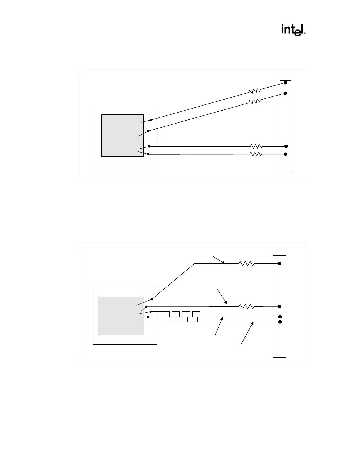
Figure 6-5. Trace Length Matching Requirements for Source Synchronous Routing
MCH
L
o
n
g
e
s
t
S
t
r
o
b
e
(
D
Q
S
)
=
Y
Shortest Data (DQ) = Y – 100 mils
Shortest Strobe (DQS) = X
L
o
n
g
e
s
t
D
a
t
a
(
D
Q
)
=
X
+
1
0
0
m
i
l
s
Rs
Rs
Rs
Rs
DIMM
Figure 6-6. DQS To CMDCLK Pair Length Matching
MCH
DIMM
CMDCLK length = x
CMDCLK# length = x
Shortest DQS length = x - 1.75"
Longest DQS length = x + 1.75"