System Bus Routing Guidelines
54 Design Guide
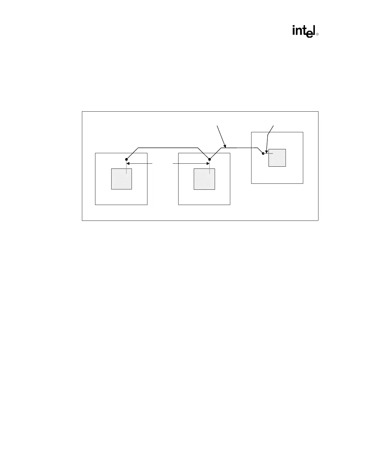
The dual processor topology requires that the MCH be at one end of the bus, Processor 0 be at the
other end of the bus, and Processor 1 be in the middle of the bus (Figure 5-1). The motherboard
routing to Processor 1 must not create a stub on the system bus signals at the socket. This requires
routing into the socket and back out of the socket. For UP operation, the single processor must be
installed in the Processor 0 socket, at the end of the bus. Figure 5-1 shows the recommended dual
processor topology used for system bus routing.
Refer to Table 5-2 for a summary of the dual processor system bus routing recommendations. Use
this as a quick reference only. The following sections provide more detailed information for each
parameter. Intel strongly recommends simulation of all signals to ensure the design meets setup and
hold times.
Figure 5-1. Dual Processor System Bus Topology
Processor 0
Processor 1
MCH
Motherboard Trace
3.0 – 10.1" 3.0 – 10.1"
Package Trace
Package
Traces