Design Guide 187
Schematic Checklist
Schematic Checklist 13
13.1 Processor Schematic Checklist
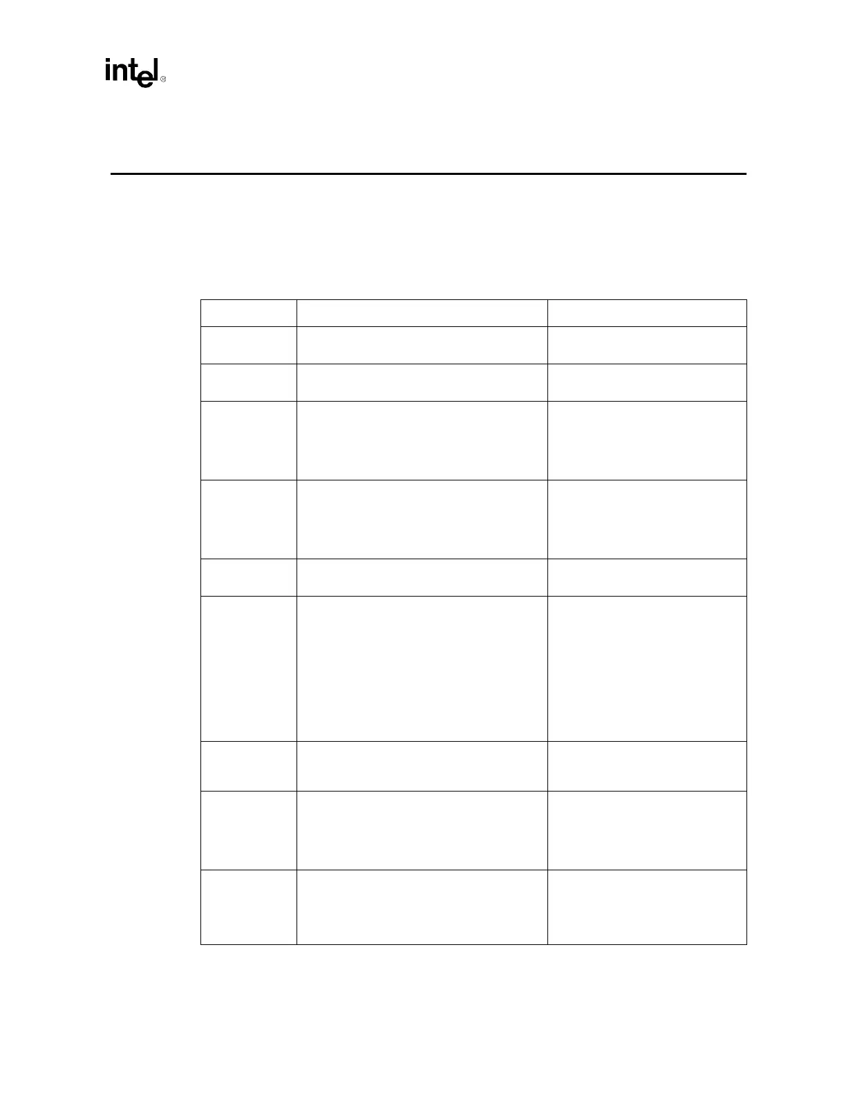
Table 13-1. Processor Schematic Checklist (Sheet 1 of 6)
Checklist Items Recommendations Comments
A20M# • Connect to both processors and ICH3-S.
Include 200
Ω ± 5% pull-up to VCC_CPU.
• Asynchronous GTL+ Input Signal.
• Refer to Section 5.3.2.
A[35:3]#
1
• Connect to both processors and the MCH. • AGTL+ Source Synchronous I/O.
• Refer to Section 5.1.
ADS# • Connect to both processors and the MCH. • Asserted to indicate the validity of
the transaction address on the
A[35:3]#
1
pins.
• AGTL+ Common Clock I/O.
• Refer to Section 5.2.
ADSTB[1:0]#
2
• Connect to both processors and the MCH. • Address strobes used to latch
A[35:3]#
1
on rising and falling
edge.
• AGTL+ Strobes.
• Refer to Section 5.1.
AP[1:0]# • Connect to both processors and the MCH. • AGTL+ Common Clock I/O.
• Refer to Section 5.2.
BCLK[1:0] • Connect to a 49.9
Ω 1% pull-down and to a
series resistor (20 – 33
Ω). Connect other
side of series resistor to CK-408.
• All processor system bus agents
must receive these signals to
drive their outputs and latch their
inputs.
• System Bus Clock.
• Refer to Section 4.1.1.
NOTE: BCLK[1:0] are processor pin
names that are connected to clocks in
the Host_CLK clock group on
CK408B.
BINIT# • Connect to both processors and the MCH.
• Wired-OR signal: Route as common clock
signal.
• AGTL+ Common Clock I/O.
• Refer to Section 5.2.
BNR# • Connect to both processors and the MCH.
• Wired-OR signal: Route as common clock
signal.
• Used to assert a bus stall by any
bus agent who is unable to accept
new bus transactions.
• AGTL+ Common Clock I/O.
• Refer to Section 5.2.
BPM[5:0]# • AGTL+ Common Clock I/O.
• For all ITP interface signal
schematic, layout and routing
recommendations, refer to the
ITP700 Debug Port Design Guide.