Design Guide 87
Hub Interface
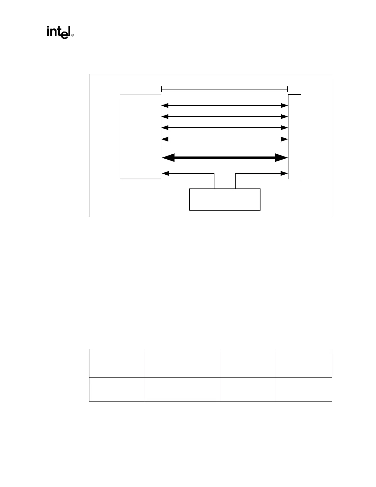
NOTE: The 14 inch maximum length allows for a single connector and 3 inch adaptor card trace length. The
PCI connector is an equivalent 3 inch electrical length. The maximum motherboard trace length must be
shortened if additional trace is allocated for the trace of a riser card, making sure to also subtract the
additional equivalent trace of a second connector.
7.2.2 Hub Interface 2.0 Generation/Distribution of Reference
Voltages
The nominal Hub Interface 2.0 reference voltage is 0.350 V ± 5%. Each Hub Interface 2.0 on the
MCH has a dedicated HIVREF pin to sample this reference voltage. Similarly, the P64H2 has a
dedicated reference voltage pin. In addition to the reference voltage, a reference swing voltage
must be supplied to control buffer voltage swing characteristics. The nominal Hub Interface 2.0
reference swing voltage should be 0.8 V ± 5% for the MCH and P64H2. Each Hub Interface 2.0 on
the MCH has a dedicated HISWNG pin to sample this reference swing voltage. The P64H2 has a
dedicated reference swing voltage pin as well. Both of these reference voltages can be generated
locally with a single voltage divider circuit. Figure 7-5 shows an example voltage divider circuit.
Figure 7-4. Hub Interface 2.0 Routing Guidelines for Hub Interface Connector Solutions
MCH
C
o
n
n
e
c
t
o
r
CK408B
CLK66 CLK66
PSTRBF
PSTRBS
PUSTRBF
PUSTRBF
HI_[21:0]
3" - 14"
Table 7-4. Hub Interface 2.0 Reference Circuit Specifications
Reference Voltage
Specification (V)
Reference Swing Voltage
Specification (V)
1.2 V Voltage DIvider
Circuit
Recommended
Resistor Values (
Ω)
1.8 V Voltage DIvider
Circuit
Recommended
Resistor Values (Ω)
0.350 ± 5%
For P64H2 = 0.8 ± 5%
For MCH = 0.8 ± 5%
R1 = 392 ± 1%
R2 = 499 ± 1%
R3 = 453 ± 1%
R4 = 261 ± 1%
R5 = 332 ± 1%
R6 = 750 ± 1%