Platform Power Delivery Guidelines
178 Design Guide
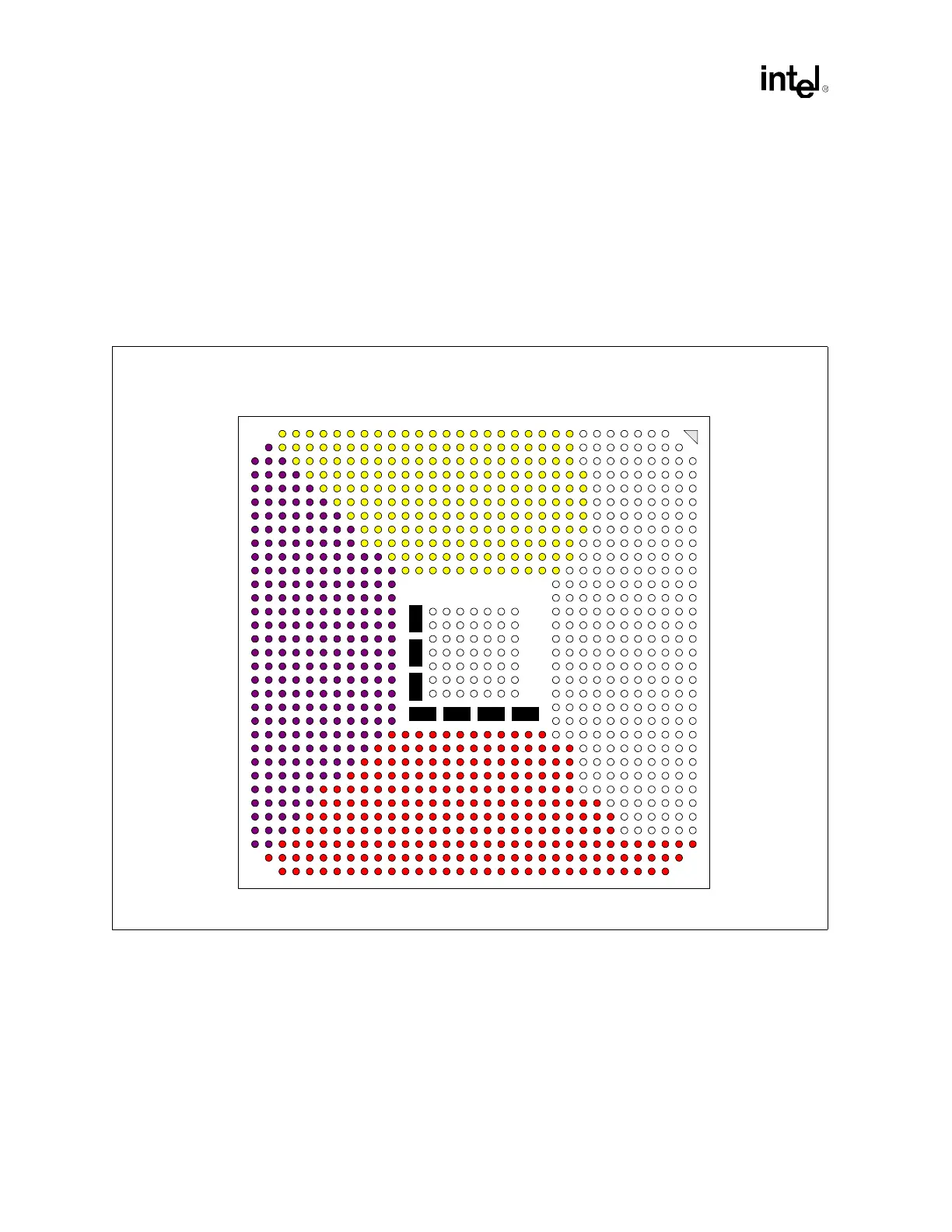
12.3.3 DDR (2.5 V Power Plane)
A maximum of seven 0.1µF (minimum of five) capacitors are recommended (with 900 pH to
1.1 nH inductance) to be placed under the MCH for DDR 2.5 V power plane decoupling
(see Figure 12-15). The designer should evenly distribute placement of decoupling capacitors
among the DDR interface signal field. It is recommended that the designer use ceramic capacitor
0402 or 0805 body type. In addition to the minimum decoupling capacitors under the MCH, the
designer should place a maximum of fifteen (15) evenly spaced capacitors for both DDR channels,
and at least ten must be within 0.5 inch of the outer row of balls to the MCH.
12.3.4 Hub Interface (1.2 V Power Plane)
A maximum of four, 0.1 µF capacitors should be used to improve I/O power delivery to the MCH.
These capacitors should be placed within 150 mils of the MCH package, adjacent to the rows that
contain the hub interface. If the layout allows, wide metal fingers running on the VSS side of the
board should connect the VCC1.2 side of the capacitors to the VCC1.2 power pins. Similarly, if
layout allows, metal fingers running on the VCC1.2 side of the board should connect the ground
side of the capacitors to the VSS power pins.
Figure 12-15. MCH Decoupling (Backside View)
DDR A
DDR B
System
Bus
HI_A–D
AM
AN
AL
AK
AJ
AH
AF
AG
AE
AD
AC
AB
Y
AA
W
V
U
T
P
R
N
M
L
K
H
J
G
F
E
D
C
B
A
AM
AN
AL
AK
AJ
AH
AF
AG
AE
AD
AC
AB
Y
AA
W
V
U
T
P
R
N
M
L
K
H
J
G
F
E
D
C
B
A
333231302928272625242322212019181716151413121110987654321
333231302928272625242322212019181716151413121110987654321
805 805 805805
805 805 805