Memory Interface Routing Guidelines
82 Design Guide
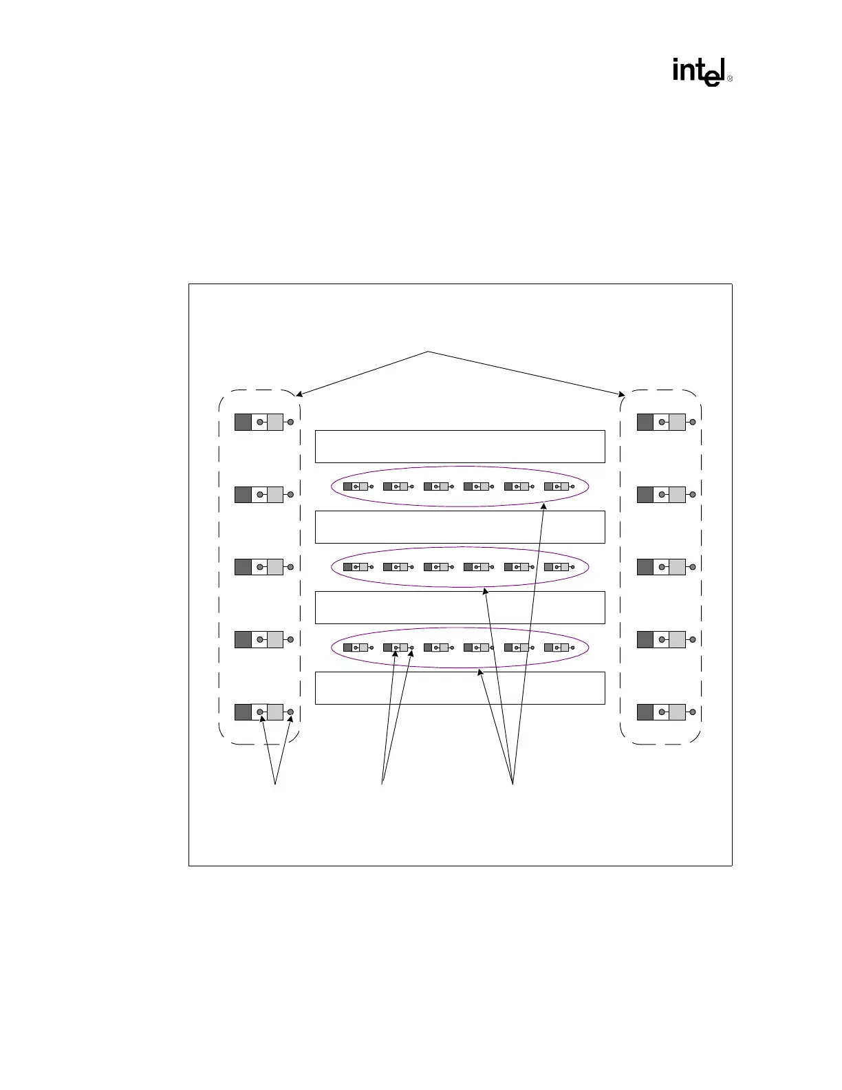
6.11 Decoupling Requirements
Decouple the DIMM connectors as shown in Figure 6-19. Place six ceramic 0.1 µF (0603)
capacitors between adjacent DIMM connectors. Place ten Tantalum 100 µF capacitors per channel
around the DIMM connectors, keeping them within 0.5" of the edge of the DIMM connectors.
Again, be sure to implement two vias per capacitor (ceramic and tantalum) to the internal ground
plane.
Figure 6-19. DIMM Decoupling
DIMM
DIMM
DIMM
DIMM
10 Tantulum 100 µF
Capacitors/Channel
Around DIMMs
6 Ceramic 0.10 µF Caps
(0603) Between DIMM
Pairs
2 Vias Per Capacitor to
Internal Ground Plane