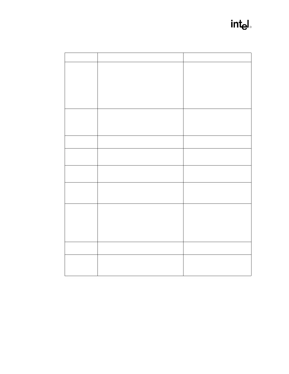
Schematic Checklist
192 Design Guide
TESTHI[6:0] • Option 1: Recommend separate 50 Ω ± 20%
pull-up to VCC_CPU.
• Option 2: TESTHI[3:0] and TESTHI[6:5] may
all be tied together and pulled up to
VCC_CPU with a single 50
Ω resistor if
desired. However, boundary scan test
cannot be performed if these pins are
connected together. TESTHI4 must always
be pulled up independently from the other
TESTHI pins.
• Input.
• Refer to Section 5.3.8.
THERMTRIP# • Connect to both processors, power control
logic and, if supported, a Baseboard
Management Controller (BMC). Pull-up at
both ends of the signal with 56
Ω ± 5%
resistors to VCC_CPU.
• Disables the VCC_CPU supply to
the processors should it ever
become asserted.
• Asynchronous GTL+ Output.
• Refer to Section 5.3.1.
TRDY#
8
• Connect to MCH and both processors. • AGTL+ Common Clock Input.
• Refer to Section 5.2.
VCCA • Use discrete RLC filter to provide clean
power.
• An isolated power for internal
PLL.
• Refer to Section 12.2.8.
VCCIOPLL • Use discrete RLC filter to provide clean
power.
• An isolated power for internal
PLL.
• Refer to Section 12.2.8.
VCCSENSE • Isolated low impedance
connection to processor core
VCC_CPU.
• Refer to Section 12.2.3.
VID[4:0] • Should be routed individually from each
processor to the voltage regulator supplying
its VCC_CPU supply. Refer to
VRM 9.1 DC-
DC Converter Design Guidelines
for VRM
details.
• Compare VIDs from both processors using
glue logic to disable VR/VRM if VIDs of both
processors do not match.
• Processor drives these signals to
indicate maximum core voltage
allowed. SM_VCC must be
correct and stable before the VRM
should rely on these outputs.
VSSA • Use discrete RLC filter to provide clean
power.
• Isolated ground for internal PLLs.
• Refer to Section 12.2.8.
VSSSENSE • An isolated low impedance
connection to processor core
VSS.
• Refer to Section 12.2.3.
NOTES:
1. A[35:3]# pins on the processor correspond to HA[35:3]# pins on the MCH.
2. ADSTB[1:0]# pins on the processor correspond to HADSTB[1:0]# pins on the MCH.
3. D[63:0]# pins on the processor correspond to HD[63:0]# pins on the MCH.
4. DSTBN[3:0]# pins on the processor correspond to HADSTBN[3:0]# pins on the MCH.
5. DSTBP[3:0]# pins on the processor correspond to HADSTBP[3:0]# pins on the MCH.
6. REQ[4:0]# pins on the processor correspond to HREQ[4:0]# pins on the MCH.
7. The RESET# pin on the processor corresponds to the CPURST# pin on the MCH.
8. The TRDY# pin on the processor corresponds to the HTRDY# pin on the MCH.
Table 13-1. Processor Schematic Checklist (Sheet 6 of 6)
Checklist Items Recommendations Comments