Design Guide 217
Layout Checklist
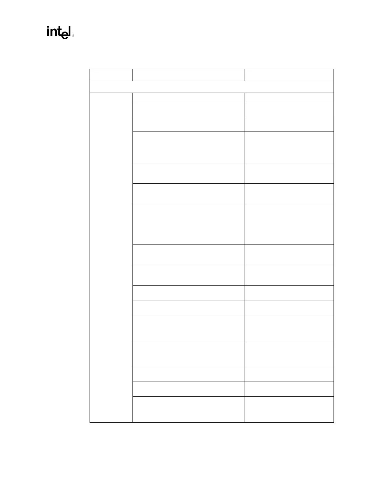
LAN Interface
General
Guidelines
• Traces: 5 mils wide, 10 mil spacing. • Refer to Section 9.7.
• LAN Max Trace Length ICH3-S to CNR:
L = 3" to 9" (0.5" to 3" on card).
• To meet timing requirements.
• Stubs due to R-pak CNR/LOM stuffing option
should not be present.
• To minimize inductance.
• Maximum Trace Lengths:
– ICH3-S to 82562EH: L = 4.5" to 10"
– 82562ET: L = 3.5" to 10"
– 82562EM: L = 3.5" to 10".
• To meet timing requirements.
• Maximum mismatch between the length of a
clock trace and the length of any data trace
is 0.5" (clock must be the longest trace).
• To meet timing and signal quality
requirements.
• Maintain constant symmetry and spacing
between the traces within a differential pair
out of the LAN phy.
• To meet timing and signal quality
requirements.
• Keep the total length of each differential pair
under 4".
• Issues found with traces longer
than 4":
– IEEE phy conformance
failures
– excessive EMI and or
degraded receive BER.
• Do not route the transmit differential traces
closer than 100 mils to the receive
differential traces.
• To minimize crosstalk.
• Distance between differential traces and any
other signal line must be at least 100 mils.
(300 mils recommended).
• To minimize crosstalk.
• Route 5 mils on 7 mils for differential pairs
(out of LAN phy).
• To meet timing and signal quality
requirements.
• Differential trace impedance should be
controlled to be ~100
Ω.
• To meet timing and signal quality
requirements.
• For high-speed signals, the number of
corners and vias should be kept to a
minimum. If a 90-degree bend is required,
use two 45-degree bends.
• To meet timing and signal quality
requirements.
• Traces should be routed away from board
edges by a distance greater than the trace
height above the ground plane.
• This allows the field around the
trace to couple more easily to the
ground plane rather than to
adjacent wires or boards.
• Do not route traces and vias under crystals
or oscillators.
• This prevents coupling to or from
the clock.
• Trace width to height ratio above the ground
plane should be between 1:1 and 3:1.
• To control trace EMI radiation.
• Traces between decoupling and I/O filter
capacitors should be as short and wide as
practical.
• Long and thin lines are more
inductive and would reduce the
intended effect of decoupling
capacitors.
Table 14-3. Intel
®
ICH3-S Layout Checklist (Sheet 2 of 4)
Checklist Items Recommendations Comments