Layout Checklist
218 Design Guide
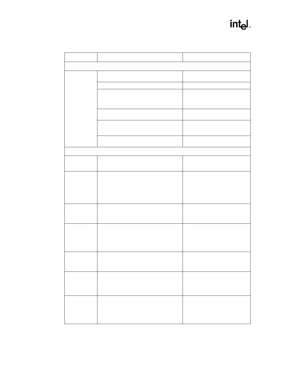
LAN Interface (Continued)
General
Guidelines
• Vias to decoupling capacitors should be
sufficiently large in diameter.
• To decrease series inductance.
• Isolate I/O signals from high speed signals. • To minimize crosstalk.
• Avoid routing high-speed LAN or Phone line
traces near other high-frequency signals
associated with a video controller, cache
controller, processor, or other similar device.
• To minimize crosstalk.
• Place the 82562ET/EM part more than 1.5"
away from any board edge.
• This minimizes the potential for
EMI radiation problems.
• Place at least one bulk capacitor (4.7 µF or
greater OK) on each side of the 82562ET/
EM.
• Research and development has
shown that this is a robust design
recommendation.
• Place decoupling capacitors (0.1 µF) as
close to the 82562ET/EM as possible.
Power Decoupling
V_CPU_IO[2:0] • Use one 0.1 µF decoupling capacitor. Locate
within 100 mils of the ICH3-S processor
interface balls.
• Used to pull-up all processor I/F
signals.
VCC_3.3 • Requires six 0.1 µF decoupling capacitors.
Distribute around the ICH3-S package sides
within 100 mils from the package balls:
– Top near AUX/PCI
– Left across the PCI and LPC
– Bottom near IDE.
VCCSUS_3.3 • Requires two 0.1 µF decoupling capacitors.
Place one capacitor on the top side within
200 mils of the USB center. Place other on
bottom side near the VCCSus3_3 supply.
VCC_1.8 • Requires four 0.1 µF decoupling capacitors.
Locate two capacitors distributed local to the
hub interface; within 50 mils of the package
hub interface balls. Distribute remaining
capacitors on the left and bottom sides of the
package for core delivery.
VCCSUS_1.8 • Requires one 0.1 µF decoupling capacitor.
Locate within 200 mils of balls B23 and C23
of the
ICH3-S.
V5_REF_SUS • Requires one 0.1 µF decoupling
capacitor.V5_REF_Sus affects only 5 V-
tolerance for USB OC[5:0]# balls, and can
be connected to VCCSus3_3 if 5 V tolerance
on these signal is not required.
V5_REF • Requires one 0.1 µF decoupling capacitor.
V5REF is the reference voltage for 5V
tolerant inputs in the ICH3-S. Tie to balls
V5REF[2:1]. V5REF must power up before
or simultaneous to VCC3_3. It must power
down after or simultaneous to VCC3_3.
Table 14-3. Intel
®
ICH3-S Layout Checklist (Sheet 3 of 4)
Checklist Items Recommendations Comments