Schematic Checklist
206 Design Guide
PA_133EN
PB_133EN
• Enable PCI-X at 133 MHz for PCI Bus A. This
pin, when high, allows the PCI-X segment to
run at 133 MHz when PA_PCIXCAP is
sampled high. When low, the PCI-X segment
will run only at 100 MHz when PA-PCIXCAP is
sampled high.
– For 133 MHz (max) PCI-X capable slot:
8.2 k
Ω ± 5% pull-up resistor to VCC_3.3.
– For 100 MHz (max) PCI-X capable slot:
8.2 k
Ω ± 5% pull-down resistor to ground.
• Only active if PA_PCIXCAP and
PB_PCIXCAP pins are high,
respectively.
Interrupt Interface
PAIRQ[15:0]
PBIRQ[15:0]
• Unused PxIRQ lines should be terminated
using an 8.2 k
Ω ± 5% pull-up resistor to
VCC3.3.
APICCLK
APICD[1:0]
• If APIC is not used, terminate using an
8.2 k
Ω ± 5% pull-up resistor to VCC3.3.
Hot Plug Interface
PCIXCAP
(On P64H2 Hot
Plug Interface)
• If implementing hot plug, PCIXCAP should be
pulled up to VCC3.3 through an 8.2 k
Ω ± 5%
resistor.
• Unused inputs should not float.
M66EN
(On P64H2 Hot
Plug Interface)
• If implementing hot plug, M66EN should be
pulled up to VCC3.3 through a 5 k
Ω ± 5%
resistor.
• Unused inputs should not float.
SWITCH • Connect to MRL Sensor. Open MRL should
pull HxSWITCH to VCC3.3. Closed MRL
should pull HxSWITCH to GND.
PRSNT1#
PRSNT2#
• Pull-up to VCC3.3 through a 5.6 k
Ω ± 5%
resistor.
• If implementing Attention Button, PRSNT1# is
the XOR of the momentary push-button and
Slot Present signal.
PxAD[63:32]
PxC/BE[7:4]
PxPAR
PxPAR64
PxREQ64#
PxACK64#
PxFRAME#
PxIRDY#
PxTRDY#
PxSTOP#
PxDEVSEL#
PxPLOCK#
PxPERR#
PxSERR#
PxREQ[5:0]#
• If implementing hot plug, pull up to VCC3.3
through an 8.2 k
Ω ± 5% resistor.
• See PCI 2.2 specification.
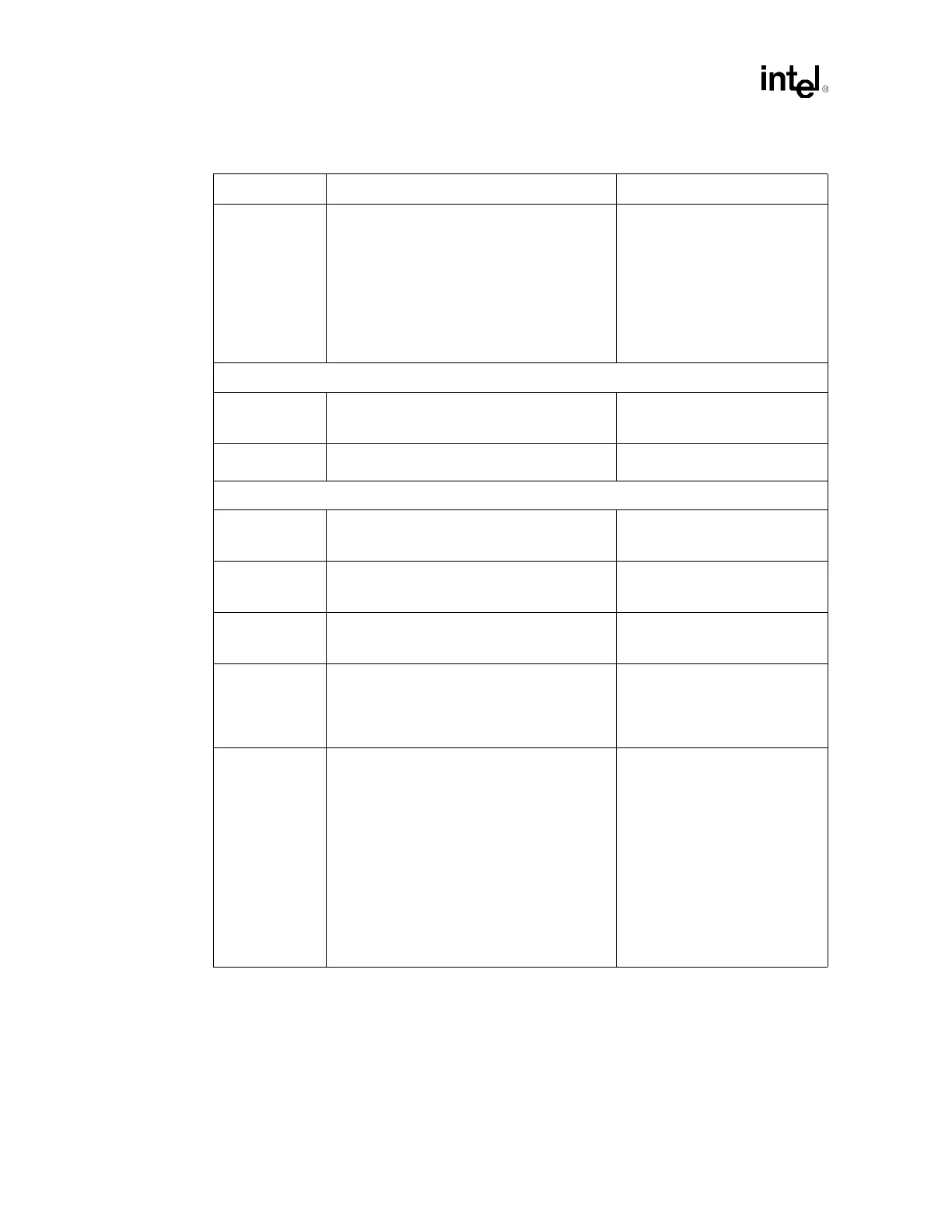
Table 13-4. Intel
®
P64H2 Schematic Checklist (Sheet 3 of 5)
Checklist Items Recommendations Comments