Image 6.14: Schematic diagram of a linear scale
①
Pitchperiods(TP):(P 542[0] - ENC_CH1_Lines)
②
Referencemarks
③
Increment-codedreferencemeasureA(smallreferencemarkinterval)(P 610[0]
- ENC_CH1 Nominalinkrement A)
④
Increment-codedreferencemeasureB(largereferencemarkinterval)(P 611[0]
- ENC_CH1 Nominalinkrement B)
Legend for Schematic diagram of a linear scale
Homing methods for increment-coded encoders
l Method-6:Increment-codedencoderswithnegativedirectionofrotation
l Method-7:Increment-codedencoderswithpositivedirectionofrotation
ID No.: 0842.26B.5-01Date: 09.2020
ServoOne- Device Help
108
6 Encoder
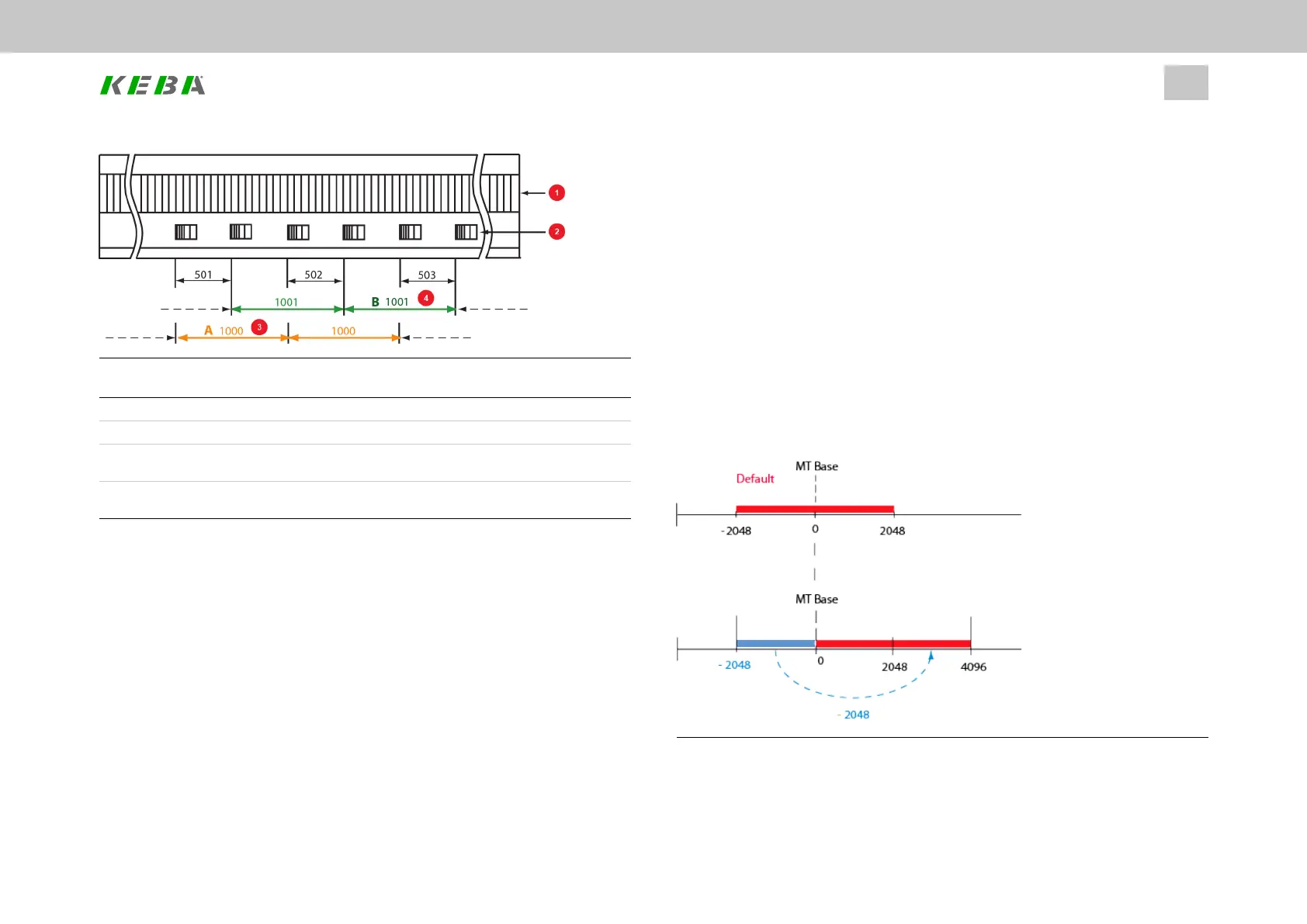
6.14Overflowinmulti-turnrange
With this function the multi-turn range can be shifted in order to avoid a possible
overflow. The function is available for encoder channels 1 and 3.
Example
If a portion of the travel distance is to the left of the threshold (MT Base), it is
appended to the end of the travel range (to the right of the 2048) via parameter
P547[0] - ENC_CH1_MTBase for encoder channel 1 and P584[0] - ENC_CH3_ for
encoder channel 3 (unit: increments).
For more information see Section "Main parameters for encoder channel Ch1" on
page 60 andSection "SinCos incremental encoders with absolute value interface" on
page 66.
Image 6.15: Multi-turn range shifting