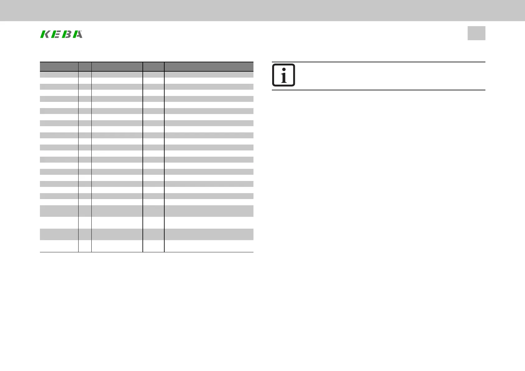
ID Index Name Unit Description
640 4 ENDAT_BWZ_4 lowbyte vn4:positionvalueformation
640 5 ENDAT_Status EnDatadditionalstatusoutput
640 6 ENDAT_Z1_Sel EnDatadditionalinformation1typeselection
640 7 ENDAT_Z1_1 Z1info:dword1
640 8 ENDAT_Z1_2 Z1info:dword2
640 9 ENDAT_Z1_3 Z1info:dword3
640 10 ENDAT_Z1_4 Z1info:dword4
640 11 ENDAT_Z2_Sel EnDatadditionalinformation2typeselection
640 12 ENDAT_Z2_1 Z2info:dword1
640 13 ENDAT_Z2_2 Z2info:dword2
640 14 ENDAT_Z2_3 Z2info:dword3
640 15 ENDAT_Z2_4 Z2info:dword4
640 16 ENDAT_Mode1 0=off EnDatadditionalmode1selection
640 17 ENDAT_Mode2 EnDatadditionalmode2selection
640 18 ENDAT_Mode3 EnDatadditionalmode3selection
640 19 ENDAT_Mode4 EnDatadditionalmode4selection
640 20 ENDAT_res1 reserved1
640 21 ENDAT_res2 reserved2
640 22 ENDAT_res3 reserved3
640 23 ENDAT_HwSyncStop 0=SyncOn EnDatcyclichwsync,stop/start1/0
640 24 ENDAT_CyclCount callcounterofcyclicfunction
640 25 ENDAT_BWZ_Supported vnsupported(bit3=vn4,bit2=vn3,bit0=vn1)
640 26 ENDAT_BWZ1_
ThresholdLevel
vn1:bits[7..0]thresholdlevel,bits[31..16]
howoftennumber
640 27 ENDAT_BWZ3_
ThresholdLevel
vn3:bits[7..0]thresholdlevel,bits[31..16]
howoftennumber
640 28 ENDAT_BWZ4_
ThresholdLevel
vn4:bits[7..0]thresholdlevel,bits[31..16]
howoftennumber
640 29 ENDAT_BWZ_TEST_
Overwrite
vn:bits[15..12]'F',bits[11..8]vn.no.,bits
[7..0]vnoverwritevalue
Table 6.8: Channel 1 encoder configuration (X7) - EnDat parameters (continue)
6.5.4HallsensorX7
Ch1: HALL(5) - Digital hall signals
Ch1: HALL_TTL(7) - Digital hall signals
ID No.: 0842.26B.5-01Date: 09.2020
ServoOne- Device Help
64
6 Encoder
NOTE
l TheoperationandconfigurationofHalleffectsensorsisreserved
forspecialapplications.ConsultwithKEBAifneeded.
6.5.5SinCos/TTLX7
6.5.5.1TTLencoder
Ch1: TTL(3) - TTL signals
TTL encoders are ...
a. ......usuallypureincrementalencoderswithoutanabsolutevalueinterface.
Inthiscase,P 540[0] - ENC_CH1_AbsmustbesettoOFF(0).
b. ......inafewexceptionalcases,incrementalencoderswithanSSIabsolute
valueinterface.Inthiscase,P 540[0] - ENC_CH1_Absmustbeaccordingly
settoSSI(1)(SSI_CONT(4)inspecialcases),sothatitwillbepossibleto
readtheabsoluteencoderpositionfortheabsolutevalueinitialization
routineonceduringtheinitializationphase.
6.5.5.1.1PureTTLincrementalencoder
Set P505[0] - ENC_CH1_Sel to TTL(3) and P540[0] - ENC_CH1_Abs to OFF(0)
when using pure TTL encoders, i.e. encoders without an absolute value interface but
with a TTL zero pulse.
Linear TTL encoders are run as rotary encoders. For linear motor operation, P542
[0] - ENC_CH1_Lines and the encoder gearing (see the “Encoder gearing” section)
are used to establish the ratio for the linear motor’s pole pair subdivision (North-
North) for commutation. 1 x North-North corresponds to one revolution from Lines. In
this case, the motor pole pair number must be set to 1. Moreover, P553[0] - ENC_
CH1_PeriodLen is not used in this case.