7.4.2Digitalfilter
To filter any noise on the actual speed value, or to damp resonance frequencies,
various filter combinations can be used. A range of filter variants are available. The
coefficients of the transfer function are automatically determined as soon as the
values for the middle and limit frequency and the width have been entered.
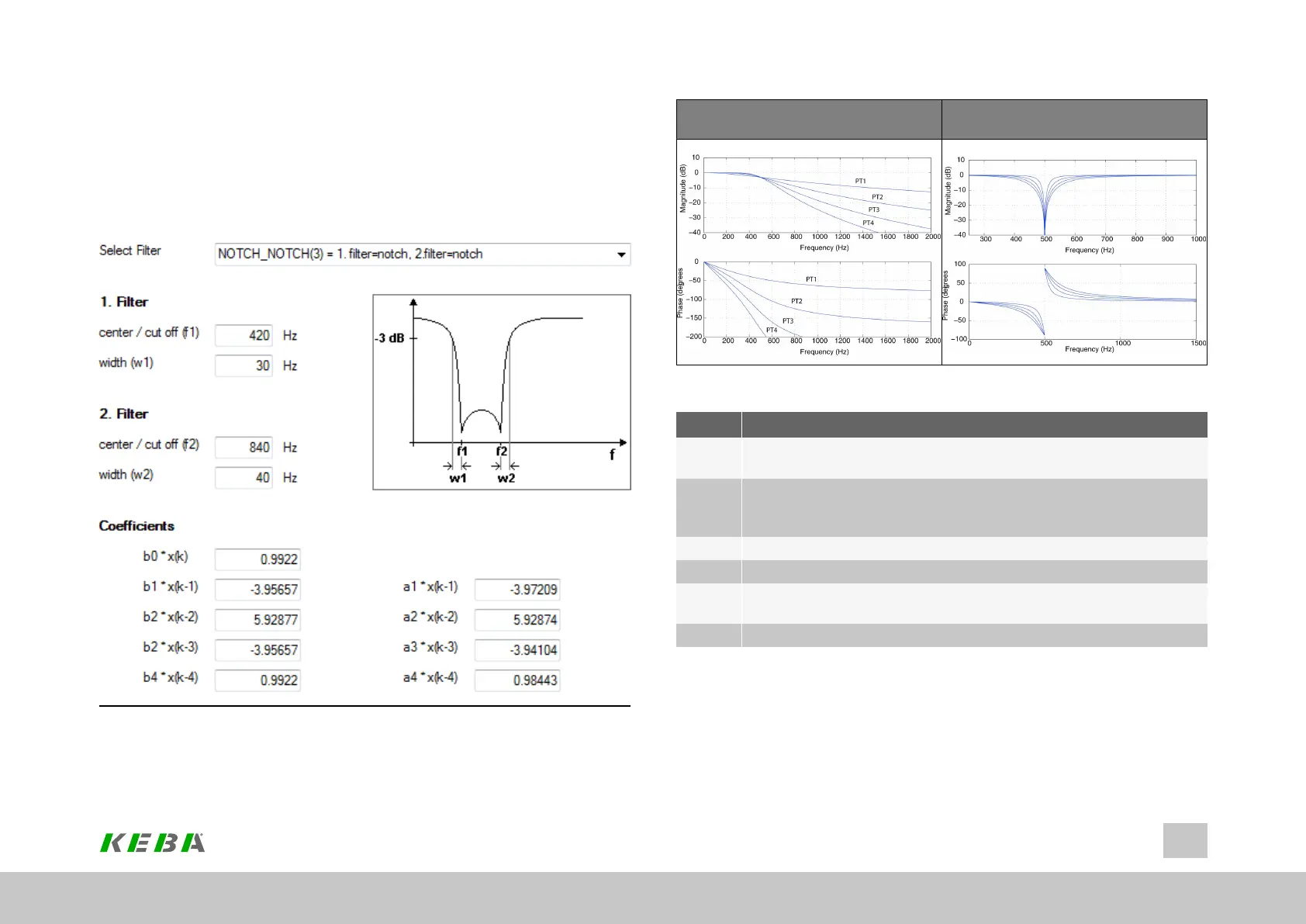
Image 7.25: “Speed controller - Digital filter” screen
ID No.: 0842.26B.5-01Date: 09.2020
ServoOne- Device Help
138
7 Control
Bode diagrams PT1 to PT4
Bode plots for band-stop filters (notch
filters)
Table 7.14: Filter Bode plots
No. Action
1
Scopesetting:isq(unfiltered,torque-formingcurrent)Setshortest
samplingtimeCreatescopeplotwithoutnotchfiltering
2
Ontheoscilloscopeclickthe"Mathematicalfunctions">FFT(Fourier
analysis)icon.Fromthefollowingpop-upmenuchooseisq.Disturbance
frequencyisdisplayed.
3 Selectfilter
4 Entermiddle/limitfrequency
5
Width:Enterthebandwidthofthelimitfrequency;thewidthhasnoeffect
whenusingPTxfilters
6 Createscopeplotwithnotchfiltering
Table 7.15: Instructions for FFT signal analysis