7.8.2LHMES(2)method
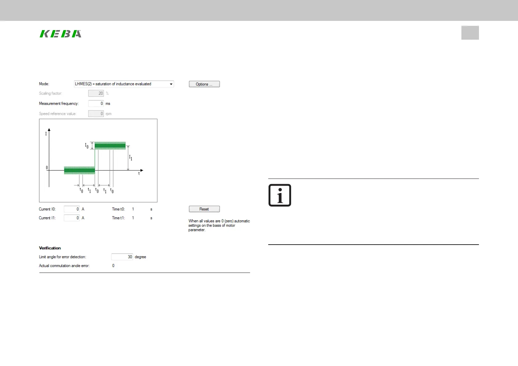
Image 7.39: “Auto commutation LHMES(2)” screen
With this method, saturation effects in stator inductance are evaluated. Two test
signal sequences are used for this purpose, whereby the position of the rotor axis is
ID No.: 0842.26B.5-01Date: 09.2020
ServoOne- Device Help
161
7 Control
known after the first sequence and the direction of movement after the second. This
method is suitable for determining the rotor position with braked rotors or motors with
a high mass inertia.
l Thetestsignalperiod(measurementfrequency)isdefinedwithP 392[2] -
CON_ICOM_Time.Ifthisvalueis0,thecontrollerusesadefaulttestsignal
frequencyof100Hz(period10ms).
l Thetestsignal’samplitude(currentI0)isdefinedwithP 393[0] - CON_
ICOM_Current.Ifthevalueis0,theamplitudeisderivedfromthemotorrated
current.Ifanamplitudegreaterthantheswitchingfrequency-dependent
powerstagecurrentisspecified,theamplitudeislimitedtohalfthepower
stagecurrent.
l Thetestsignal’sDCcomponent(currentI1)isdefinedwithP 393[1] - CON_
ICOM_Current.Ifthisvalueis0,theequalportionisdeterminedfromthe
motorratedcurrent.
NOTE
l Asimpleparametersettingisobtainedbyspecifyingthevalue0
forP 392[2] - CON_ICOM_Time,P 393[0] - CON_ICOM_Current
andP 393[1] - CON_ICOM_Current.Theparametersarethen
assigneddefaultvalueswhicharederivedfromthemotor/power
stagecurrent.Thenthemeasurementisperformed.
l InordertobeabletousethecomplexLHMESautocommutation
methodtoitsfullextent,youwillneedtoconsultwithKEBA.
Precondition
The rotor must be securely braked so that it will not be able to move when the rated
current is applied. The stator of the machine must be iron-core.