ID Index Name / Setting Unit Description
7 ENCPOS_CH3(7)=Encoderposition
Channel3
8 ENCPOS_CH3_INC(8)=Encoderposition
Channel3inincrements
9 ENCPOS_CH4(9)=Encoderposition
Channel4
10 ENCPOS_CH4_INC(10)=Encoder
positionChannel4inincrements
11 ACTPOS2(11)=Actualpositionof
redundantencoderinuserunits
12 Sercos(12)=ReferredtoSercosprofile
parametersS-x-0426,S-x-0427
13 UserRefPos(13)=Referencepositionin
userunits
14 MasterPosST(14)=Masterposition
(ECAM,EGEAR)singleturn,alwayssteps
15 CommonMasterPos(15)=Masterposition
(ECAM,EGEAR)singleturn,alwayssteps
16 CommonMasterPosST(15)=Master
position(ECAM,EGEAR)singleturn,
alwayssteps
1402 0 MPRO_TP_Channel
1402 1 MPRO_TP_Channel
1402 2 MPRO_TP_Channel
1404 MPRO_TP_Lines Touchprobe:Lines@pulsecounteron
channelx
1404 0 MPRO_TP_Lines
1404 1 MPRO_TP_Lines
Table 8.29: “Touch probe” parameters (continue)
NOTE
l Formoreinformationrefertothebussystemusermanualsorthe
descriptionoftheiPLC.
ID No.: 0842.26B.5-01Date: 09.2020
ServoOne- Device Help
279
8 Motion profile
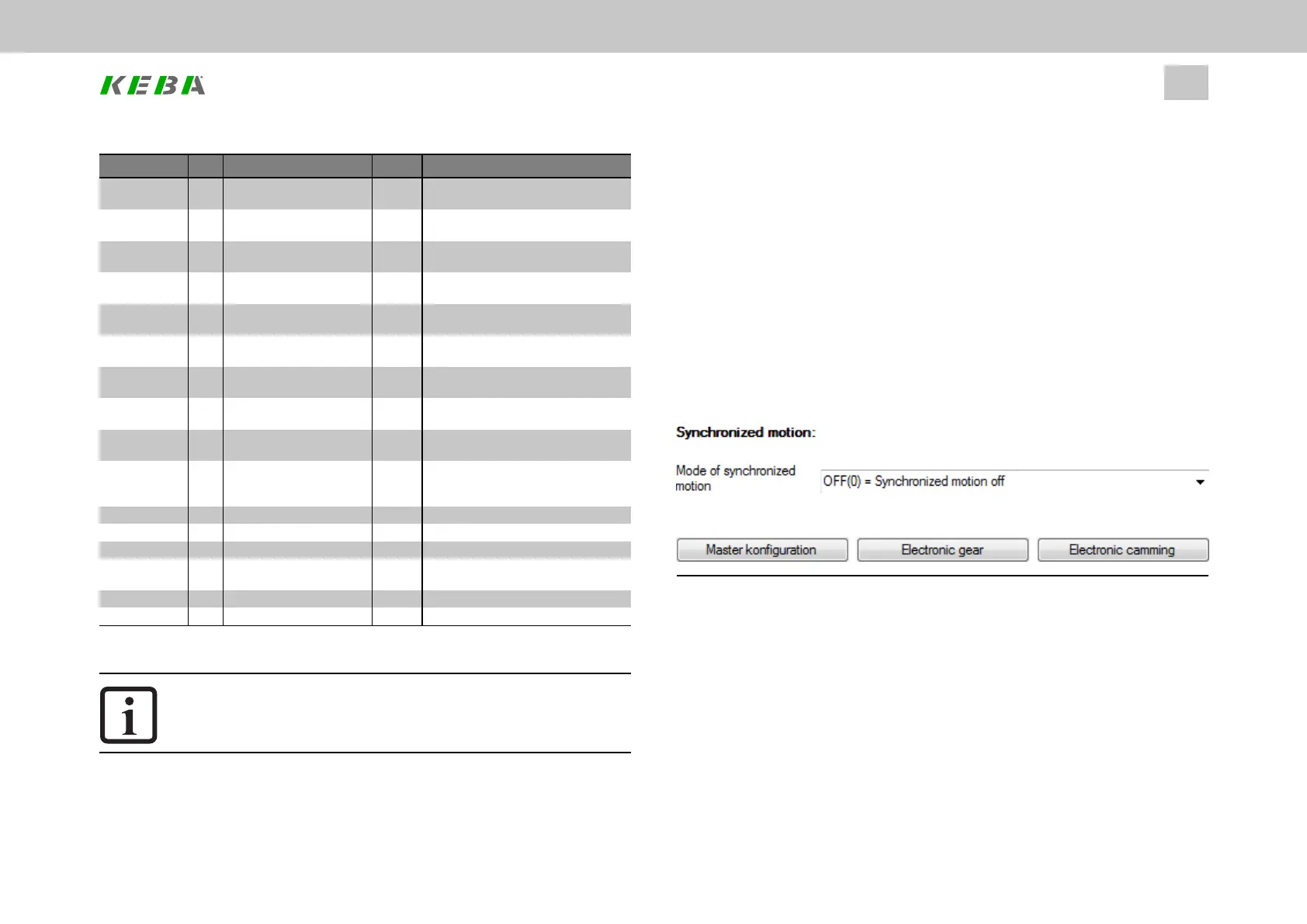
8.11Synchronizedmotion
The Synchronized Movement function enables synchronous running of the drive in
relation to a real or virtual master axis.
Digital control signals are used to provide positionally precise disengagement from
the guide value (e.g. with standstill at cycle end) and positionally precise
engagement to the current guide value.
An encoder system, the virtual master or the parameter interface is selected as the
master encoder in the master configuration. By setting the parameter interface to a
bus system (Basic setting Control and Reference) control is programmed via a bus
system.
Image 8.71: “Synchronized motion” screen
There are various modes available in the “synchronization mode” drop-down menu
(P242[0] - MPRO_ECAM_SyncModMode):
l Off(0)=Synchronizedmotionoff
l ECAM_iPlc(1)=ElectroniccamplateviaiPlc
l EGEAR_iPlc(2)=Electr.gearunitviaiPLC
l ECAM_PARA(3)=Electroniccammingviaparameters
l EGEAR_PARA(4)=Electronicgearingviaparameters