5.7SupportformotorfilterswhenusingPMSM
motors
5.7.1Generalfunctionaldescription
In applications involving high-speed drives in particular, the use of filters between
the inverter output and the motor is widespread as a measure designed to attenuate
current harmonics. The following two are used for this purpose:
l Motorchokes
l LCfilters,alsoreferredtoas“sinewavefilters”
A motor choke basically increases the stator inductance and, in the case of current-
controlled drives, simply results in a higher inductive voltage consumption.
Accordingly, it is not necessary to take motor chokes into account separately when
calculating current setpoints.
Meanwhile, as a result of the additional capacitor current (
i
c
) resulting from their use,
sine wave filters result in a change to the current vector between the inverter output
(
i
inv
) and the motor (
i
s
). Accordingly, these filters must be taken into account when
calculating current setpoints in order to ensure that the motor will be run at the
desired operating point (normally with q current operation) at all speeds.
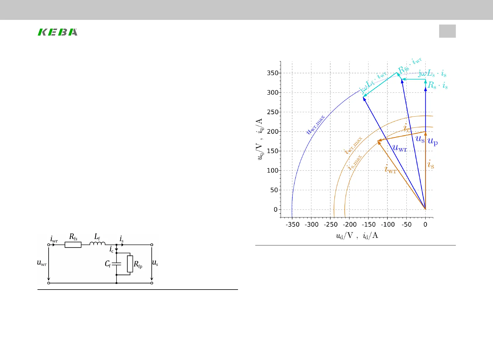
Image 5.14: Single-phase equivalent circuit diagram for a sine wave filter
ID No.: 0842.26B.5-01Date: 09.2020
ServoOne- Device Help
47
5 Motor
Image 5.15: Phasor diagram for a sine wave filter