l P 543[0] - ENC_CH1_MultiT=Numberofmulti-turnbits:0..14
DuetothedesignofthecyclicalSSIinterfaceasamotorfeedbackinterface,
thenumberofmulti-turnbitsislimitedto14(nolimitto14bitsinthecaseofa
SinCosinterfacewithSSIone-timereading).
l P 545[0] - ENC_CH1_Code=SSIdecoding:BINARY(0)orGRAY(1)
Graydecodingwillbeselectedbydefault.Theotheroptionistousebinary
decoding.
l P 546[0] - ENC_CH1_Mode=AvailableSSIauxiliarysettings
Thisparameterhasa16-bithexvalue.Withthedefaultsetting(0000h),SSI
wirebreakmonitoringwillbeenabled.Avalueof0001hwilldisableSSIwire
breakmonitoring,meaningthatonebitlesswillberead.
Followingisalistofwhatsomeofthetermsinthetablebelowstandfor:
o
Data=Sequenceofalldatabits
o
EncObs=Wirebreakbit
o
Nothing=Nobit
o
POdd=Oddparitybit
o
PEven=Evenparitybit
o
Free=Afreebit
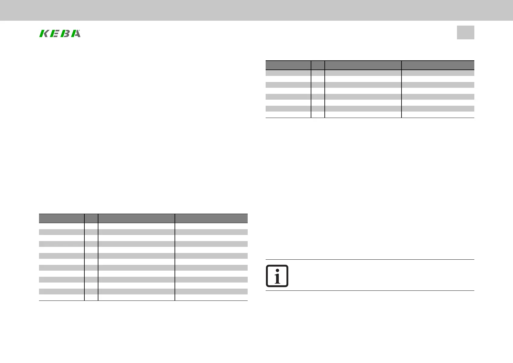
ID Value Name
546 ENC_CH1_Mode
0000h Data_EncObs Default:withwirebreak
0001h Data_Nothing
0002h Data_POdd_EncObs ODDParity
0003h Data_Free_POdd_EncObs
0004h Data_POdd
0005h Data_Free_POdd
0006h Data_Free_EncObs
0007h Data_Free_Free_EncObs
000Ch Data_PEven_EncObs EVENParity
Table 6.14: SSI mode parameters (all other values are reserved)
ID No.: 0842.26B.5-01Date: 09.2020
ServoOne- Device Help
72
6 Encoder
ID Value Name
000Dh Data_Free_PEven_EncObs
000Eh Data_PEven
000Fh Data_Free_PEven
001Fh Data_Free Extradatareading
0020h Data_Free_Free
0021h Data_Free_Free_Free
0022h Data_Free_Free_Free_Free
Table 6.14: SSI mode parameters (all other values are reserved) (continue)
P616[0] - ENC_CH1_CycleCount = Sampling cycle in: n x 125µs (microseconds):
ENC_CH1_CycleCount can be used to slow down the timing for the cyclical SSI
encoder evaluation. By default, ENC_CH1_CycleCount = 1, i.e. the default setting
corresponds to 125µs sampling and cycles for the encoder evaluation. Different
settings must be viewed as special cases and must only be used when necessary.
Monitoring the position difference
With SSI encoders, the position difference is monitored automatically. The limit value
is based on the maximum speed with reference to one scanning step (125µs). The
position difference between two scanning steps is restricted to this limit value. In the
event of an EMC disturbance, this limits the (incorrectly detected) tracking error and
the response of the controller.
6.5.7Encodergearing
NOTE
l Pleasereadthegeneralinformationonencodergearingfoundin
Section"Introduction"onpage52beforehand.
Encoder channels Ch1 to Ch3 each feature their own encoder gearing, while
encoder channel Ch4 (virtual encoders) does not feature
any
encoder gearing.