In the case of encoder channel Ch2, it is assumed that the resolver will always be
used as a commutation encoder on the motor shaft. Because of this, the numerator
adjustment range is limited to a value of (+1) or (-1), while the denominator is set at a
fixed value of (+1), for the Ch2 encoder gearing ratio. This means that the only
option available is to invert the encoder signal (direction reversal).
As a whole, the encoder gearing is a scaling factor in the encoder evaluation system
and consists of numerator N (ENC_CHx_Num) for the motor side and denominator D
(ENC_CHx_Denom) for the encoder side (output side).
The following are used to configure the encoder gearing...
l Ch1withP 510[0] - ENC_CH1_NumandP 511[0] - ENC_CH1_Denom,
l Ch2withP 512[0] - ENC_CH2_NumandP 513[0] - ENC_CH2_Denom,
l Ch3withP 514[0] - ENC_CH3_NumandP 515[0] - ENC_CH3_Denom,
parametriert.
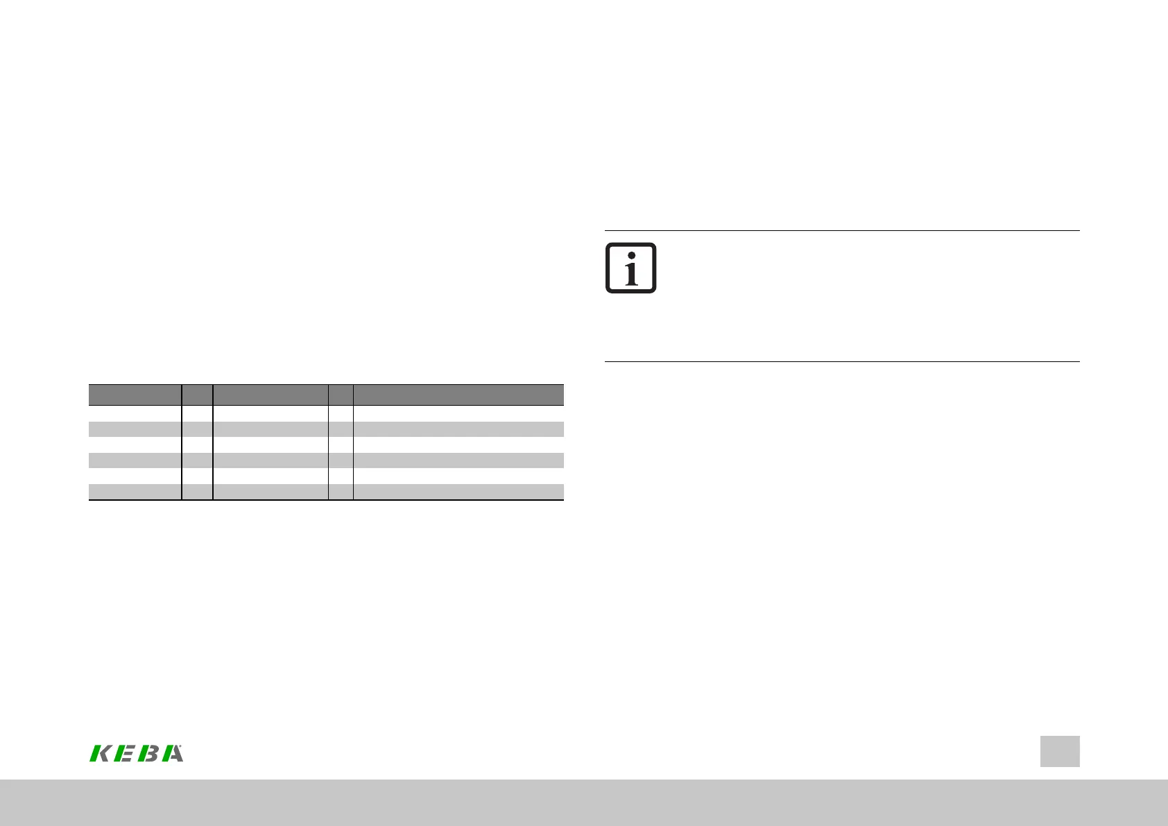
P No. Index Name Unit Description
510 0 ENC_CH1_Num Denominatorofchannel1
511 0 ENC_CH1_Denom Numeratorofchannel1
512 0 ENC_CH2_Num Denominatorofchannel2
513 0 ENC_CH2_Denom Numeratorofchannel2
514 0 ENC_CH3_Num Denominatorofchannel3
515 0 ENC_CH3_Denom Numeratorofchannel3
Table 6.15: Parameters for encoder gearing
ID No.: 0842.26B.5-01Date: 09.2020
ServoOne- Device Help
73
6 Encoder
Parameters
l P 500[0] - ENC_CH1_ActVal[0].SingleTurnand
l P 500[1] - ENC_CH1_ActVal[1].MultiTurn
are used, for example, to indicate the current position value at the output for encoder
channel Ch1. These parameters can also be used for checking purposes during
commissioning.
NOTE
l Thisvalueattheencoderchanneloutput...
o
Alreadycontainstheencodergearingratiofactor(N/D)
o
Willbepassedintothesysteminthisway(incl.the
encodergearingratio)
o
I.e.is“thevalue”fromtheencoderevaluationsystem
The encoder gearing ratio has a multiplicative effect on the position progress, i.e.
either “expanding” or “compressing”.
A distinction can be drawn between an encoder’s motor mode and field mode:
l Motormode:Theencoderisthemotorcommutationencoder
l Fieldencoder:Theencoderisnotthemotorcommutationencoder(instead,it
isanadditionalencoderinthe“field”,e.g.usedforpositioncontrolpurposes)
In motor mode, the encoder gearing is used exclusively to synchronize the motor
shaft with the encoder shaft (default: 1:1 if the shaft is the same). In this case, a
position progress value will be passed to the system at the encoder channel output.
This value will be proportional to the position progress of the motor’s commutation
(adjusted for the pole pair number).
In field mode, the encoder gearing can be used “freely” for scaling purposes.