Remote RMX-3200 Version 5.2x Configuration Guide
Configuring the Peripheral Management Subsystem: Peripheral Management Subsystem Overview
25-5
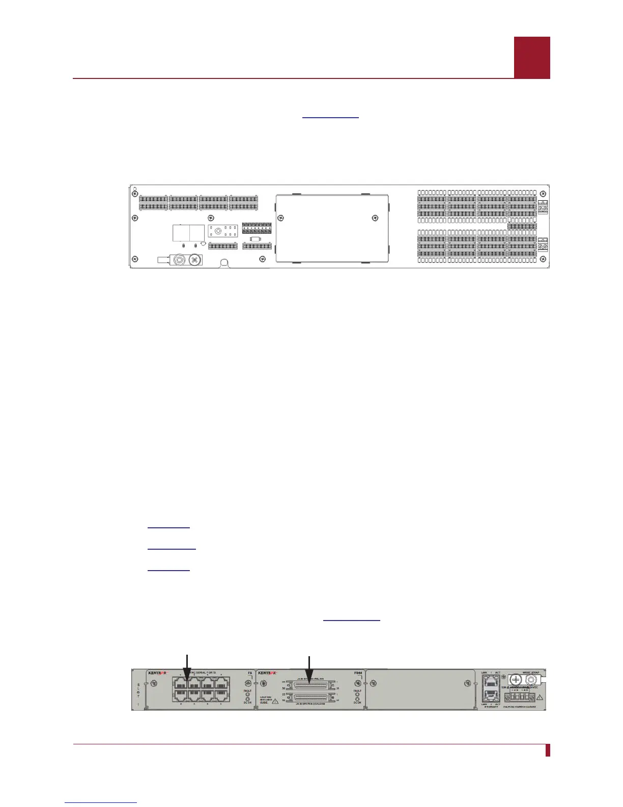
RMB-2 Peripheral Unit
The RMB-2 peripheral unit (refer to Figure 25-3) offers similar capabilities to RMB-1 in
a chassis that is sized to be easily mounted in a standard 19-inch, 21-inch, or 23-inch
rack. RMB-2’s digital bistate inputs support both wet and dry contacts, while RMB-1’s
digital bistate inputs support dry contacts only.
Figure 25-3 RMB-2 Peripheral Unit
For technical specifications on RMB-1 and RMB-2 and for details on physically
connecting to RMB terminals, see the Remote RMM-1400 Installation Guide.
RMB-1 and RMB-2 Identification
Each RMB peripheral unit has a name that is defined in the following format:
RMB1-XXXXXX
XXXXXX represents the low-order three bytes of the peripheral’s MAC address (for
example,
RMB1-0E68F4). Note that the name begins with RMB1 regardless of whether
the peripheral unit is an RMB-1 or an RMB-2.
RME-1000 Unit
The RME-1000 unit provides three expansion slots for the following plug-in
peripherals:
RME-S8
RME-B64
RME-E8
The RME-1000 provides a power supply and an Ethernet switch, but otherwise has
no intelligence. The Ethernet switch is connected to the two front panel Ethernet
connectors and to each slot in the unit.
Figure 25-4 displays the RME-1000 unit.
Figure 25-4 RME-1000 Unit with RME-S8 and RME-B64 Peripherals
RME-S8 Peripheral
RME-B64 Peripheral