9 Diagnostics & error management
9.4 Drive diagnostics via keypad/bus system
630
Lenze · 8400 HighLine · Reference manual · DMS 12.0 EN · 06/2017 · TD23
_ _ _ _ _ _ _ _ _ _ _ _ _ _ _ _ _ _ _ _ _ _ _ _ _ _ _ _ _ _ _ _ _ _ _ _ _ _ _ _ _ _ _ _ _ _ _ _ _ _ _ _ _ _ _ _ _ _ _ _ _ _ _ _
Display parameters
The parameters listed in the following tables serve to query current states and actual values of the
inverter for diagnostic purposes, e.g. by using the keypad, a bus system or the »Engineer« (with an
online connection to the inverter).
• These parameters are listed in the »Engineer« parameter list and the keypad in the Diagnostics
category.
• A detailed description of these parameters can be found in the chapter "Parameter reference
"
( 802)
.
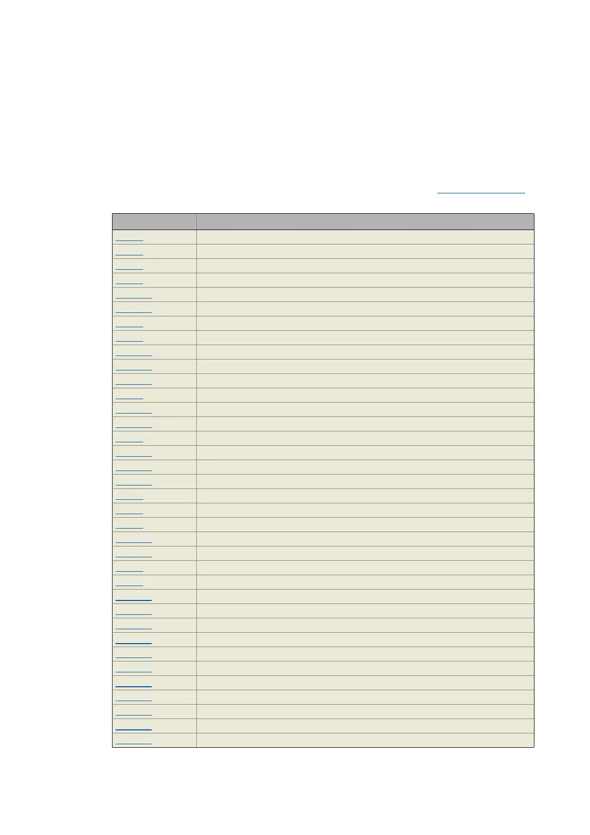
Parameters Display
C00051 MCTRL: Actual speed value
C00052 Motor voltage
C00053 DC-bus voltage
C00054 Motor current
C00056/1 Torque demand
C00056/2 Actual torque value
C00058 Output frequency
C00061 Heatsink temperature
C00064/1 Device utilisation (Ixt)
C00064/2 Device utilisation (Ixt) 15s
C00064/3 Device utilisation (Ixt) 3 min
C00133 Brake resistor utilisation
C00136/1 MCI control word
C00136/2 CAN control word
C00137 Device status
C00138/1 SYS control signals
C00138/2 MCK control signals
C00138/3 FWM control signals
C00150 Status word
C00158 Cause of controller inhibit
C00159 Cause of quick stop QSP
C00165/1 Status determining error (displayed as a numeric text)
C00165/2 Current error (displayed as a numeric text)
C00168 Status determining error (display of 32-bit number)
C00170 Current error
C00166/1 Error type, status determining
C00166/2 Error subject area, status determining
C00166/3 Error ID, status determining
C00166/4 Error type, current
C00166/5 Error subject area, current
C00166/6 Error ID, current
C00177/1 Switching cycles mains switching
C00177/2 Switching cycles output relay
C00177/3 Stress counter - short circuit
C00177/4 Stress counter - earth fault
C00177/5 Stress meter clamp

 Loading...


