2-132 Service Manual
5026
Operator panel display all diamonds, no beeps
Operator panel display all diamonds, five beeps
Print quality service check
Note: This symptom may require replacement of one or more CRUs (Customer Replaceable Units) designated
as supplies or maintenance items, which are the responsibility of the customer. With the customer's permission,
you may need to install a developer (toner) cartridge or photoconductor unit.
Service tip: Before troubleshooting any print quality problems, do the following:
1. Print a menu settings page, and then check the life status of all supplies. Any supplies that are low should
be replaced.
Note: Be sure and keep the original menu page to restore the customer's custom settings if needed.
2. On the menu page, make sure the following is set to the default level:
– Color Correction: Set to Auto.
– Print Resolution: Set to 1200 dpi (print quality problems should be checked at different resolution
settings).
– Toner Darkness: Set to 4 (default).
– Color Saver: Set to OFF.
– RGB Brightness, RGB Contrast, RGB Saturation: Set to 0.
– Color Balance: Select Reset Defaults to zero out all colors.
– Check the paper type, texture and weight settings against what is loaded in the printer.
Once the printer has been restored to its default levels, do the following:
3. Inspect the transfer module for damage. Replace if damaged.
4. Inspect the photoconductor units and toner cartridges for damage. Replace if damaged.
5. If paper other than 20 lb plain letter/A4 paper is being used, load 20 lb plain letter/A4 and print the Print
Quality pages to see if the problem remains.
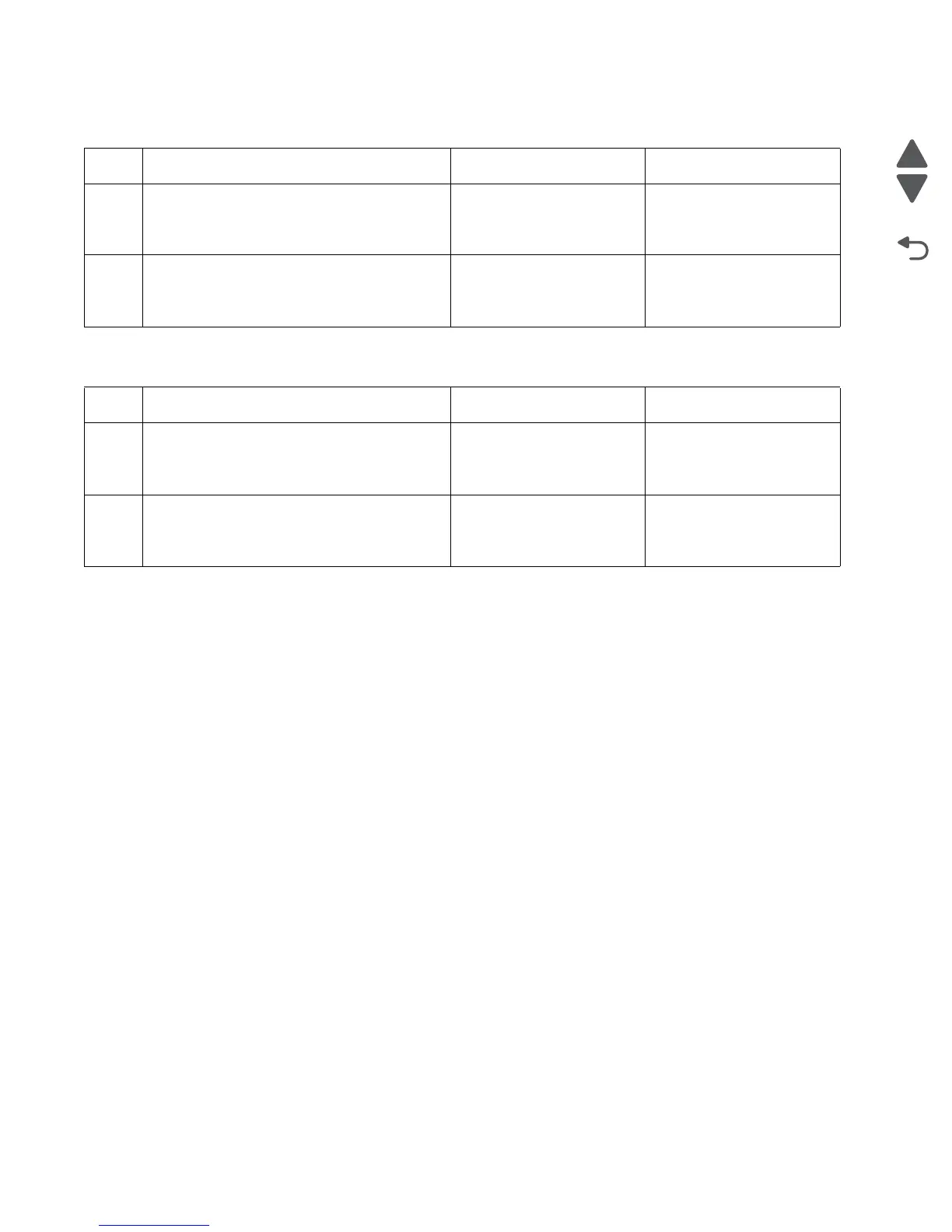
Step Questions / actions Yes No
1 Check the operator panel assembly cable.
Is the cable damaged?
Replace the top access
cover assembly. See “Top
access cover assembly
removal” on page 4-40.
Go to step 2.
2
Measure the voltage between JOPP1 pin 2
and ground on the system board.
Is the voltage approximately +5 V dc?
Replace the operator panel
assembly. See “Operator
panel assembly removal”
on page 4-24.
Replace the system board.
See “System board
removal” on page 4-153.