R–8
WHEEL ALIGNMENT
FRONT WHEEL ALIGNMENT (WGN)
A6E741201015201
Specification (Unloaded)*
1
2WD
*
1
: Engine coolant and engine oil are at specified level. Spare tire, jack and tools are in designated position.
*
2
: Difference between left and right must not exceed 1°30'.
*3
: Distance between wheel center and fender brim is 405 mm {15.94 in} (reference value).
4WD
*
1
: Engine coolant and engine oil are at specified level. Spare tire, jack and tools are in designated position.
*
2
: Difference between left and right must not exceed 1°30'.
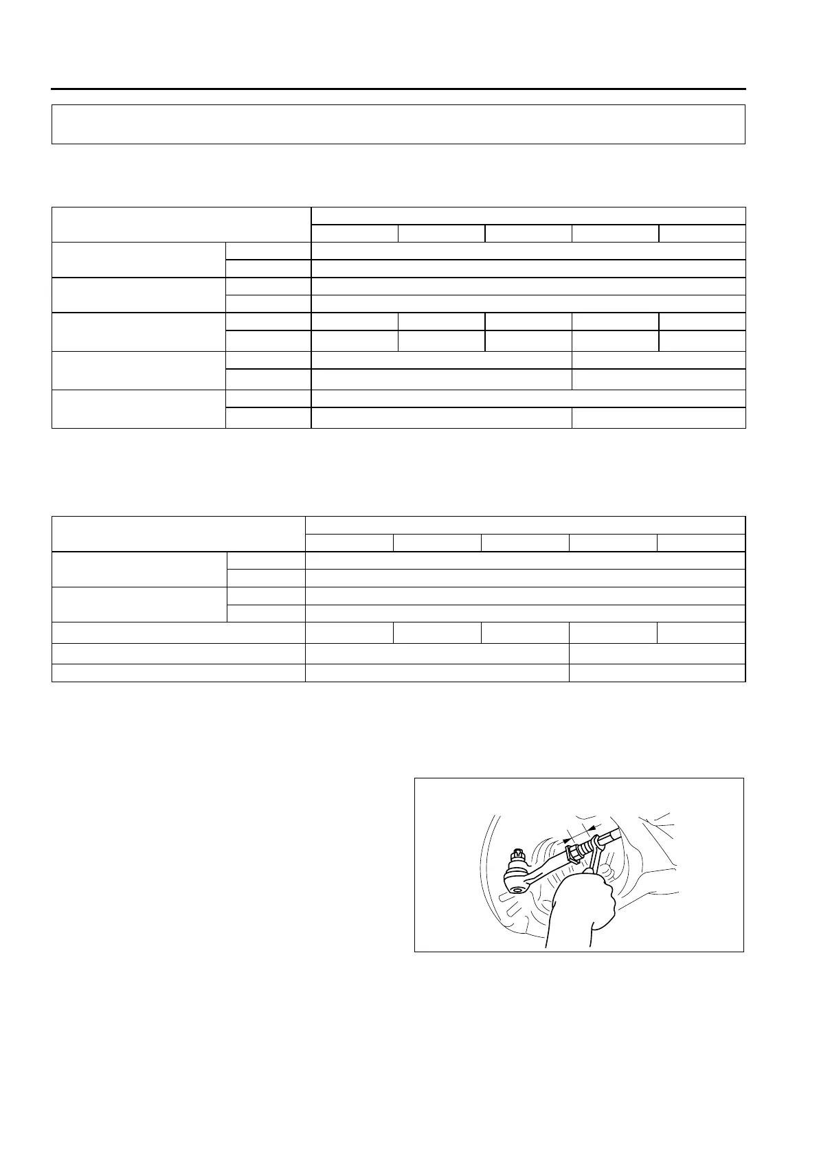
Maximum Steering Angle Adjustment
1. Loosen the tie-rod end locknuts.
2. Remove the steering gear boot clamp.
3. Turn the tie rods to equalize the length L.
Maximum left/right difference
3 mm {0.12 in}
4. Turn the tie rods equally to provide the correct
maximum steering angle.
5. Tighten the tie-rod end locknuts.
Tightening torque
68.6—98.0 N·m {7.00—9.99 kgf·m, 50.6—72.2
ft·lbf}
6. Verify that the boot is not twisted, and install the
boot clamp.
7. Adjust the toe-in after adjusting the steering angle.
WHEEL ALIGNMENT
Item
Fuel gauge indication
Empty 1/4 1/2 3/4 Full
Maximum steering angle
Inner 39°±3°
Outer 31°±3°
Total toe-in
(mm {in}) Tire: 2±4 {0.08±0.16}, Rim inner: 1±3 {0.04±0.12}
(degree) 0°11′±0°22′
Caster angle
*2
(Reference value)
normal 3°30'±1° 3°32'±1° 3°34'±1° 3°37'±1° 3°40'±1°
elevated
*3
3°25'±1° 3°27'±1° 3°29'±1° 3°32'±1° 3°35'±1°
Camber angle
*2
(Reference value)
normal -0°14'±1° -0°15'±1°
elevated
*3
-0°07'±1° -0°08'±1°
Steering axis inclination
(Reference value)
normal 5°24'
elevated
*3
5°15' 5°16'
Item
Fuel gauge indication
Empty 1/4 1/2 3/4 Full
Maximum steering angle
Inner 39°±3°
Outer 31°±3°
Total toe-in
(mm {in}) Tire: 2±4 {0.08±0.16}, Rim inner: 1±3 {0.04±0.12}
(degree) 0°11′±0°22′
Caster angle*
2
(reference value)
3°25'±1° 3°27'±1° 3°29'±1° 3°32'±1° 3°35'±1°
Camber angle*
2
(reference value)
-0°07'±1° -0°08'±1°
Steering axis inclination (reference value) 5°15' 5°16'
LEFT AND RIGHT DIFFERENCE
L
LESS THAN 3 mm {0.12 in}
A6E7412W002










 To Next Page