SERVICE PROCEDURES REQUIRING MINOR DISASSEMBLY
SERVICE MANUAL NUMBER 28
90-863160 MAY 2000 Page 4A-15
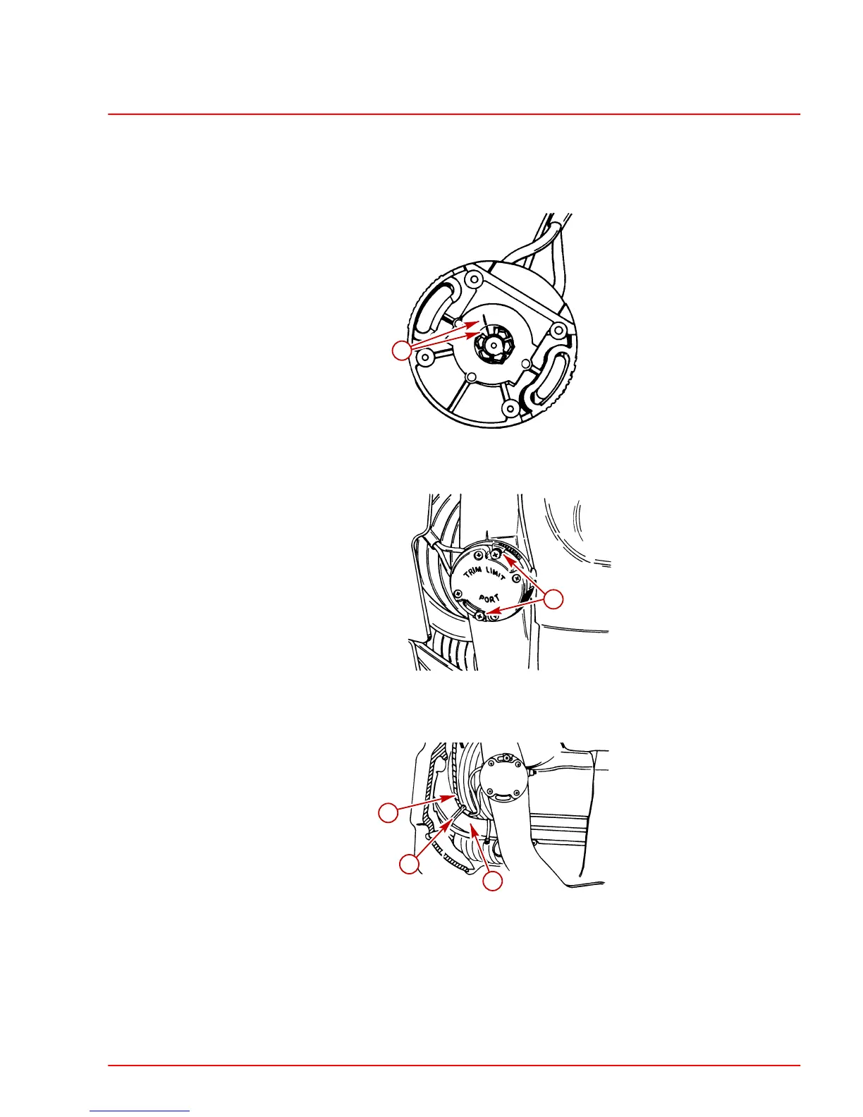
6. Reinstall trim limit switch as follows:
a. Place sterndrive unit in full DOWN/IN position.
b. Turn center rotor of trim position sender to align index mark with index mark on
sender body.
71218
a
a-Index Marks
c. Install trim limit switch and secure with attaching hardware.
71221
a
a-Attaching Hardware
7. Secure the trim limit switch harness to the water hose with the plastic clip.
71184
a
b
c
a-Plastic Clip
b-Trim Limit Switch Harness
c-Water Hose
8. Reconnect trim position sender wires to engine harness and the trim limit leads to trim
pump harness.
9. Reinstall battery cables.
 Loading...


