REMOVAL, INSTALLATION AND ADJUSTMENTS
SERVICE MANUAL NUMBER 28
90-863160 MAY 2000 Page 2A-25
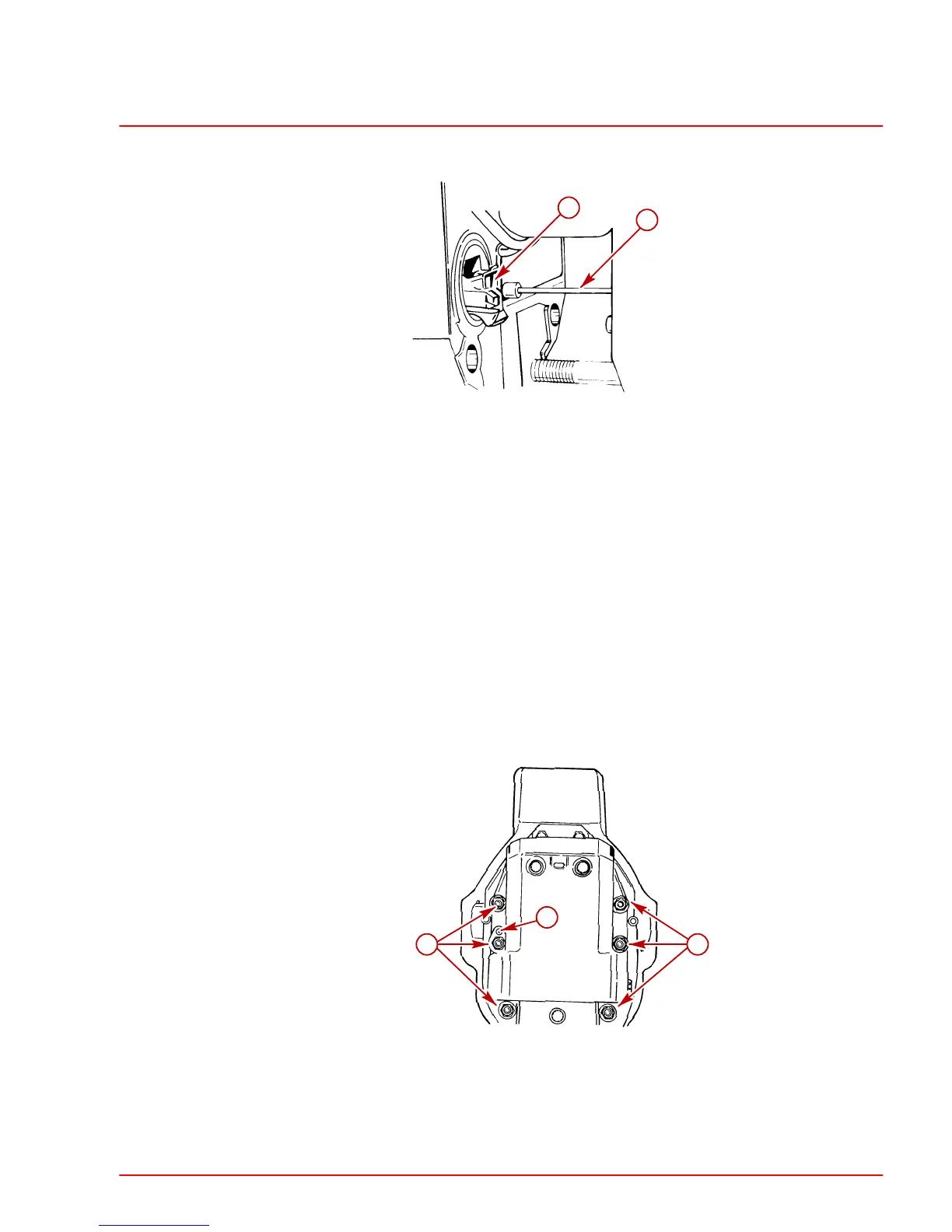
NOTE: If the shift cable does not line up to properly enter the shift linkage jaws, use your
hand to guide the cable into place while installing the sterndrive unit.
22025
a
b
a-Shift Linkage Jaws
b-Shift Cable
9. Install the sterndrive unit.
a. Position the trim cylinders so that they point straight backwards (aft).
b. Align the U–joint shaft with the bell housing bore. Make sure the studs on the bell
housing align with the appropriate holes on the sterndrive unit.
c. Guide the U-joint shaft through the gimbal bearing and into the engine coupler. Make
sure that the shift linkage jaws engage with the shift cable.
d. If necessary, rotate the propeller shaft slightly to align the U-joint shaft splines with
the engine coupler splines, then slide the sterndrive unit completely into the bell
housing.
e. Rotate the propeller shaft slightly to ensure that the sterndrive unit is still in neutral
once installed.
10. Fasten the sterndrive unit to the bell housing. Start from the center and torque the nuts
to 50 lb-ft (68 Nm).
22031
b
aa
a-Locknuts (6) and Flat Washers (5)
b-Ground Plate (Flat Washer Not Used Here)
 Loading...


