2
Names and Functions of Parts
Cha
ter 1
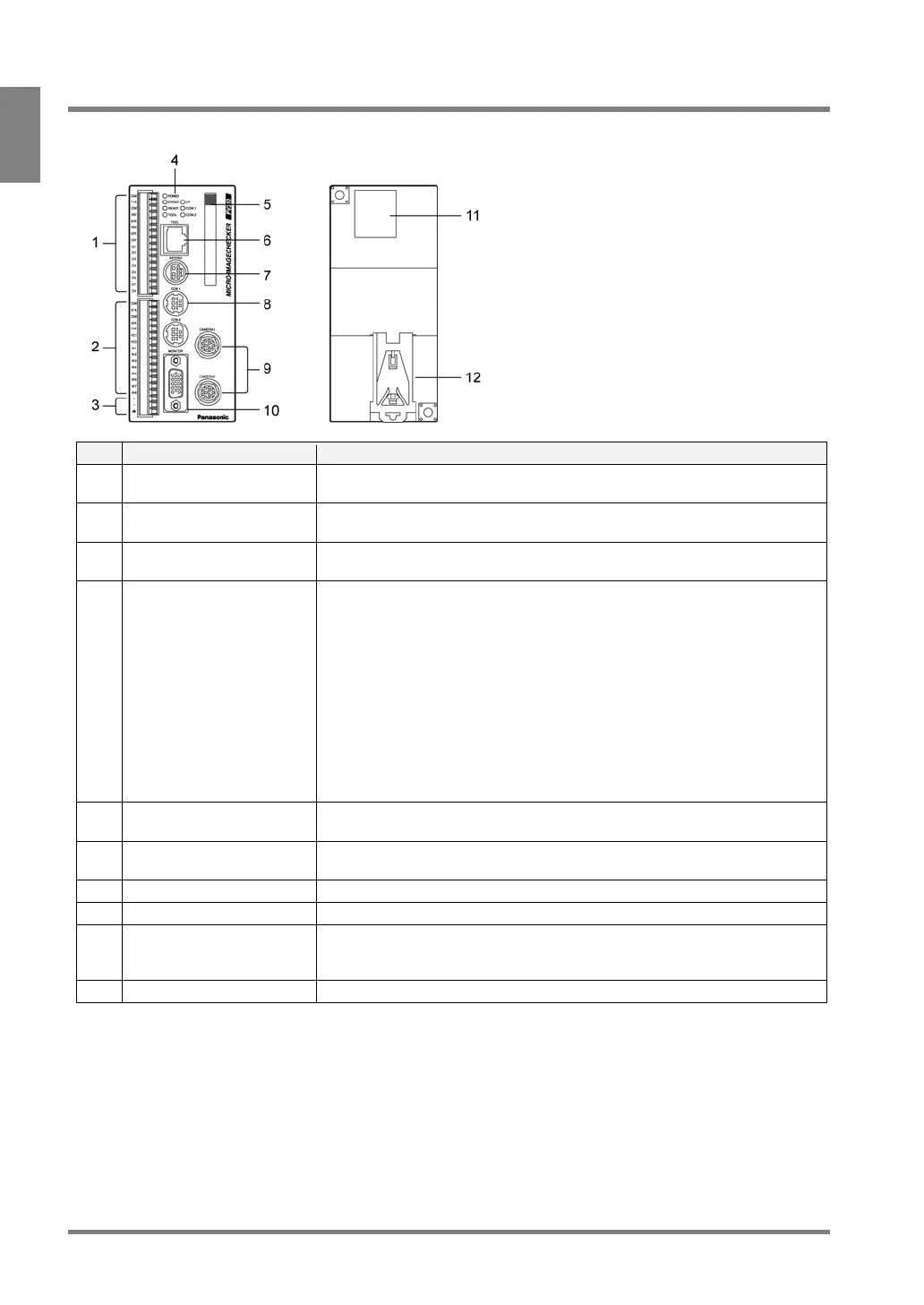
1.1 About PV310
Front Back
No. Name Description
1 External output terminal (16
pins)
An external output terminal block (by Phoenix), product #: 1840502.
2 External input terminal (15
pins)
An external input terminal. COMMON terminal is for +/-. An external output
terminal block (by Phoenix), product #: 1840528.
3 Power terminal Acceptable input voltage is 24V DC. The power terminal is located on the
input terminal block.
4 Operating LEDs Indicate the operating status of the PV310.
• POWER (green):
The green POWER LED lights when the PV310 is being energized.
• ERROR (red):
The red ERROR LED lights when an error is detected.
• READY (green):
The green READY LED lights when the PV310 is ready to receive the
signals including start signal from the external device
• CF: The green CF LED lights when the PV310 is accessing the Compact
Flash memory card.
• COM1: The green COM1 LED lights when serial communication is
established.
5 Compact Flash* memory
card slot
Supports for a FAT16- formatted Compact Flash memory card (Max. 512MB )
6 TOOL port
(Ethernet* Port)
Connects to the external device via Ethernet port. Use a cross cable when
connecting between an external device and a PV310.
7 KEYPAD connector Connects to the operation keypad.
8 COM port (RS-232C port) Connects to the external device via the COM port. COM2 is not available.
9 Camera connectors Can connect to up to two cameras: CAMERA 1 and CAMERA 2. Using a
camera switching unit enables you to connect to maximum four standard
cameras.
10 MONITOR Connects to the VGA monitor