5
Names and Functions of Parts
Cha
ter 1
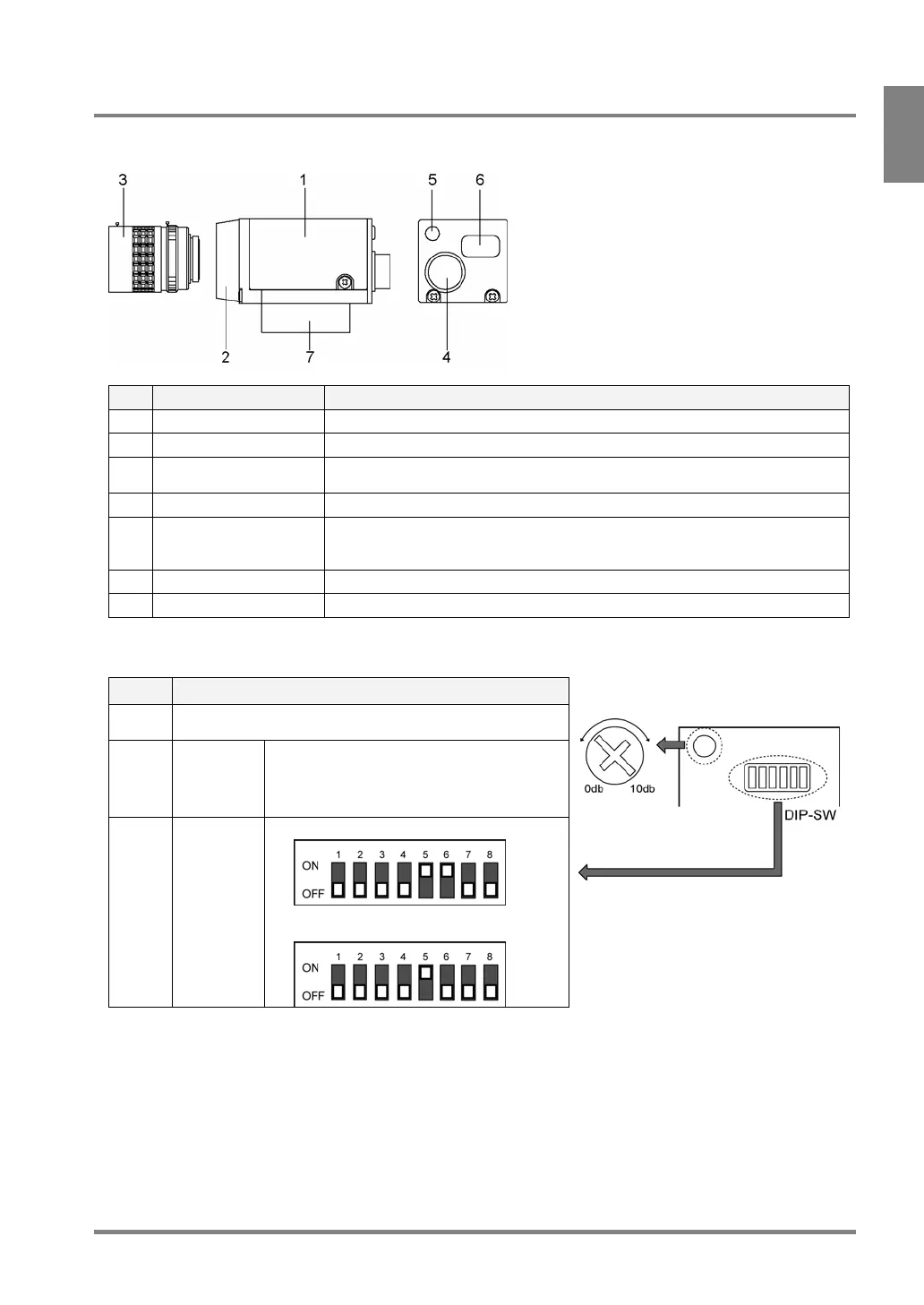
1.2.2 Double Speed Random Camera: ANM831
This camera is usable when the camera setting of PV310 is [D.S. Random Frame] or [D.S. Random Field].
No. Name Description
1 Camera Body of camera
2 Lens fixture C-mount
3 Lens Attach a C-mount lens with adapter rings as necessary. Refer to page 21 for
selecting view range and lens.
4 Cable connector Connects to the controller with a camera cable. (ANM84303XX)
5 VOL knob for fine
adjustment of gain
Makes a fine adjustment for camera gain
When DIP switch No.5 is ON, turning this knob clockwise makes a capturing
image brighter.
6 DIP switch Switches camera modes and activates gain adjustment.
7 Mounting plate A plate to mount a camera. The plate insulates with the mounting surface.
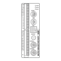
About DIP Switch (DIP-SW)
No. Description
1-4, 7,
8
Always leave OFF
5 Gain fine
adjustment
• ON: Allows you to make fine adjustment
within the range between 0 and +10 dB
using the VOL knob
• OFF: 0 dB
6* Camera
mode
switching
• OFF: D.S. Random Field mode (default)
• ON: D.S. Random Frame mode
Gain adjustment volume
Default settings: DIP SW No.5: ON, the rest of the dip switches: OFF, VOL knob: +10 dB
* When you changed the camera mode, change the camera mode of PV310 as well.