253
Cha
ter 10
Parallel Communication
10.5.3 Re-registering the Template
This is a function to update the template (base image) of the target checker by inputting signals from the external
device. When these signals are input, the template is updated based on the current image or memory image. The
numbers of the target checkers to be re-registered are assigned to IN 1 to 7, and then the template is
re-registered upon FCT1 (or FCT2) signal input. To do this, it is necessary to assign “Template Settings” function
to FCT1 or FCT2 signal (factory default setting of FCT2: Template Settings). Refer to Section 9, “Environment
Settings” (page218) for settings of FCT1 and FCT2 signals.
Target Checker
• Smart Matching
• Contour Matching
Re-register Mode
There are the following two modes for re-registration. For mode setting, select "Template Settings" from the
ENVIRONMENT menu.
Setting Position Re-registering can be executed in the position of the preset template area. This mode is
available if the re-registration position of the object is the same as the setting position of the
target checker.
Adjusted Position If "Position Adjustment" is set to any other number than "0", this mode re-registers the
template at the adjustment position of the target checker after position adjustment or
rotation adjustment is executed and the target checker is adjusted. This mode will be
available if the re-registration position of the object is not the same as the setting position of
the target checker.
Area Display
This is a function to check the area to be re-registered on the monitor screen before re-registering a template
after a timing signal for executing re-registration and FCT2 (or FCT1) signal are input. In this case, it is required to
input timing signals (or commands) twice. The area can be set by selecting "ENVIRONMENT" > "Template
Settings" from the menu bar.
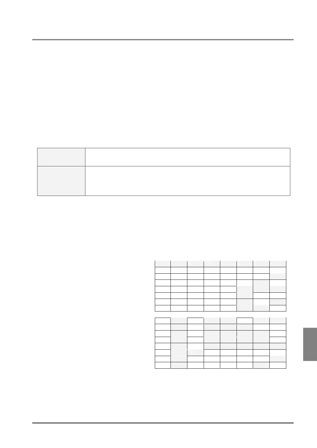
Specifying the Number of Checker to Re-Register
No. IN7 IN6 IN5 IN4 IN3 IN2 IN1
1 OFF OFF OFF OFF OFF OFF OFF
2 OFF OFF OFF OFF OFF OFF ON
3 OFF OFF OFF OFF OFF ON OFF
4 OFF OFF OFF OFF ON ON ON
5 OFF OFF OFF OFF ON OFF OFF
6 OFF OFF OFF OFF ON OFF ON
7 OFF OFF OFF OFF ON ON OFF
:
92 ON OFF ON ON OFF ON ON
93 ON OFF ON ON ON OFF OFF
94 ON OFF ON ON ON ON OFF
95 ON OFF ON ON ON ON OFF
96 ON OFF ON ON ON ON ON
97 ON ON OFF OFF OFF OFF OFF
98 ON OFF OFF OFF OFF OFF ON
Assign the numbers of the target checkers you
want to re-register to IN1 to 7 (7 bit). Specify the
value subtracted one from the actual product type
number in the binary data form. Refer to the table
shown right.
If you switch the display images when signals IN1
to IN7 are input by a combination undefined in the
table on the right of signals and display camera
images, an error signal is output.
Example) IN1 – 7 = all ON
99 ON OFF OFF OFF OFF ON OFF