32
In
ut and Out
ut Interface Ports
Cha
ter 3
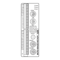
3.1.5 Output Terminals
Arrangement of the terminals
Signal Name Content
COM COMMON For FLASH only
FLA FLASH Flash sync signal
COM COMMON Common terminal for General Output
RDY READY Ready signal
ERR ERROR Error signal (refer to page 316 for
more details of error causes.)
REN READ END Image capture completion signal
STR STROB Strobe signal (Data output completion
signal during handshake )
OVF OVER FLOW
FLAG
Overflow signal (this signal is output if
the output value exceeds the data
length you have set)
D1 Data
D2 Data2
D3 Data3
D4 Data4
D5 Data5
D6 Data6
D7 Data7
D8 Data8
Data output signals
• Number of scans
• Data of Judgment
• Data of Numeric Calculation
• Data of Statistics
Output Circuit:
Product number with final number “N”
The NPN open collector output is adopted. The load current should be within the rated voltage range.
Rated operating voltage: 12 to 24 V DC
A connecting example with PLC