11
Names and Functions of Parts
Cha
ter 1
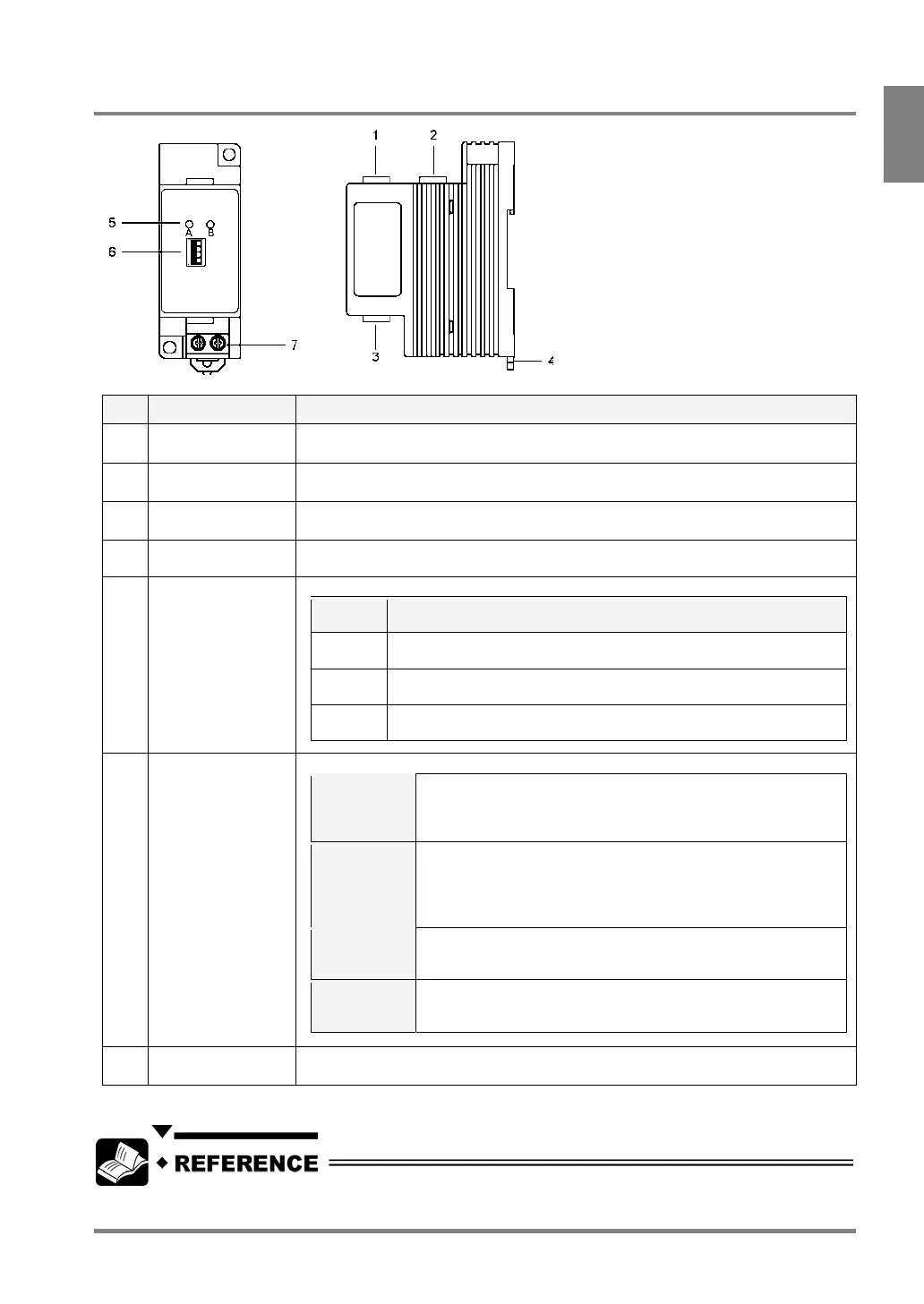
1.2.6 Camera Switching Unit: ANPV3700
No Name Description
1
Input port for
Camera A
Connects a camera. Camera A is connected to this port.
2
Input port for
Camera B
Connects a camera. Camera B is connected to this port.
3 OUT (image output)
port
Outputs images to the PV310. Use the provided cable for switching cameras.
4 DIN rail attachment
lever (one-two hook)
To attach to DIN rail with a single touch.
5 Camera A/Camera
B indicators
The indicators tell which camera is in use for capturing images.
Lighting
Lamp
Status
A only The PV310 is in camera switching mode (the dip switch 2 is placed in
the NORMAL position). The image captured by Camera A is output.
B only The PV310 is in camera switching mode (the dip switch 2 is placed in
the NORMAL position.) The image captured by Camera B is output.
A and B The PV310 is in DIV mode (the dip switch 2 is placed in the DIV
position).
6 Dip switches
(4 switches)
The four dip switches change the functions shown in the table below.
1
LOCAL /
REMOTE
If you want to switch between Camera A and Camera B using an
external device when the PV310 is in camera switching mode
(the dip switch 2 is placed in the NORMAL position), set to
“REMOTE”.
2
NORMAL
/ DIV*
If you want to switch between Camera A and Camera B (in
camera switching mode), set to “NORMAL”. If you want to
combine the upper and lower half parts of two images captured
by Camera A and Camera B in one image (in the DIV mode), set
to “DIV”.
3 A / B
This is a switch for changing the cameras to output the images in
camera switching mode (the dip switch 1 and 2 are placed in
LOCAL and NORMAL positions respectively).
4
Upper /
Lower
division
In camera division mode (the dip switch 2 is placed in the DIV
position), select a part of the images captured by Camera A and
Camera B that you want, upper half or lower half.
7 Input terminal for
external signal
This is a terminal for inputting a camera switch signal.
* A Double speed random camera: ANM831 and an Ultra small camera: ANPVCA1012 are not available in Camera
division mode.
For more information on the camera control unit, refer to Chapter 16 Camera Switching Unit (page 321).